Modules:ResampleDTIVolume-Documentation-3.4
Return to Slicer 3.4 Documentation
ResampleDTIVolume
General Information
Module Type & Category
Type: CLI
Category: Diffusion Tensor
Authors, Collaborators & Contact
- Francois Budin
- Sylvain Bouix, PNL
- Contact: Ryan Eckbo, PNL, reckbo[at]bwh[dot]harvard[dot]edu
Module Description
This module implements Diffusion Tensor Image (DTI) resampling through the use of ITK Transforms. It supports any transform that is implemented in ITK (rigid, affine, non-rigid such as BSpline, etc). 'Resampling' is performed in space coordinates, not pixel/grid coordinates. It is quite important to ensure that image spacing is properly set on the images involved. The interpolator is required since the mapping from one space to the other will often require evaluation of the intensity of the image at non-grid positions.
Usage
Examples, Use Cases & Tutorials
- This module is especially appropriate when one needs to resample an image and already knows the transform to apply to it. Its principal advantages resides in the fact that one can apply any kind of transform supported by ITK (rigid, affine and non-rigid) and can choose between the most commonly used interpolators.
- The transform can be passed as an ITK Transform file using the command line, or directly as a transform node in Slicer3. In the latter case, the transform can only be rigid or affine.
- It also allows changing the spacing, the orientation, the size and the origin of the image. In that case, the image will be modified in consequences.
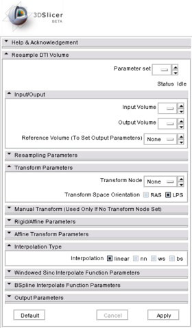
Quick Tour of Features and Use
- Input/Output: Defines input and output files.
- Input volume is the volume to resample,
- Reference Volume (optional) is the volume used to set the sampling parameters (origin, spacing, orientation and dimensions). If it is not set, the input volume will be taken for reference.
- Output volume is the name of the output.
- Resampling Parameters:
- Number Of Threads sets the number of threads used to perform the resampling.
- Correction sets if a filter is applied on the resampled image to ensure that every tensor is positive definite symmetric. Three filters are available: set to zero the negative eigen values, take their absolute values or compute their closest positive definite symmetric matrix.
- Transform Parameters: if the transform to be applied is in the slicer mrml tree, one can select it here.
- Manual Transform: if no tranform is set in previous panel, one can enter his own transform
- Transform Matrix: a 12-parameter affine transformation manually. The first 9 numbers represent a linear transformation matrix in column-major order (where the column index varies the fastest), the last 3 are a translation.
- Transform: forces the transform to be of rigid or affine type (affine is default)
- Space: It should normally not be modified when using this module directly in Slicer3 with a transform node. It does not specify whether the matrix is expressed in LPS or RAS coordinate space but rather if everything is expressed in the same coordinate space. LPS means that everything is in the same space and RAS means that it is not the case. This option can be set to RAS if the given transform is in RAS coordinate space (respectively LPS) and the input volume is in LPS coordinate space (respectively RAS). Be careful: When passing manually the transform, the coordinate space modification is directly applied on the given transform. However, when passing the transform through a file or a transform node, it is the input volume coordinate space that is modified and the transform is left unchanged (so that any kind of transform supported by ITK is also supported by this module). If one sets the output volume parameters manually, one has to pay attention to the fact that in that case the given parameters are considered to be in the transform coordinate space!!!
- Rigid/Affine Parameters:
- Rotation Point: uses a fiducial to set a point around which the rotation defined in the transform needs to be performed.
- Centered Transform: sets the center of the transformation to the center of the image.
- Inverse ITK Transformation: inverses the transformation before applying it to the image. The transform given to the module is from the output image to the input one. If one wants to specify a transform from the input image to the output image, one should use this flag. This option can only be used if the transform is rigid or affine. Be careful: if the file containing the transform contains multiple transforms, only rigid and affine transforms will be inverted.
- Affine Transformation Type: Use the Preservation of the Principal Direction (right image) to compute the affine transform. Otherwise, the Finite Strain Method (left image) is used [1] .
- Interpolation Type: sets the type of interpolation kernel to either linear, nearest neighbor (nn), windowed sinc (ws), or b-spline (bs). The windowed sinc interpolator uses a constant boundary condition whereas the b-spline interpolator uses a mirror boundary condition.
- Windowed Sinc Interpolate Function Parameters: selects the type window function for the sinc interpolation h=hamming, c=cosine, w=welch, l=lanczos, b=blackman. This is only relevant if one selects ws as the interpolation type.
- BSpline Interpolate Function Parameters: The spline order (only relevant if the selected interpolator is bs).
- Output Parameters: One can overwrite the reference volume parameters by setting manually the spacing, size, origin (as a fiducial), and direction matrix (also known as space directions) in column-major order.
Development
Dependencies
None
Known bugs
Follow this link to the Slicer3 bug tracker.
Usability issues
Follow this link to the Slicer3 bug tracker. Please select the usability issue category when browsing or contributing.
Source code & documentation
link to ResampleDTIVolume.
More Information
When Using the module in command line
- The Transform can be given through an ITK Transform file. An example is given below.
#Insight Transform File V1.0
# Transform 0
Transform: AffineTransform_double_3_3
Parameters: 1.73205080756880 0.5 0 -0.5 .8660254037844 0 0 0 1.5 15 32 27
FixedParameters: 40 35 20
- Be Careful : The transform file must have an empty line after the fixed parameters
- The Fixed Parameters are the coordinates of the center of rotation
- The Parameters are written in the following format:
- The first 9 numbers represent a linear transformation matrix in column-major order (where the column index varies the fastest)
- The last 3 are a translation.
- A transform file may contain multiple transforms. The module will apply all of them.
Acknowledgment
This work is part of the National Alliance for Medical Image Computing (NAMIC), funded by the National Institutes of Health through the NIH Roadmap for Medical Research, Grant U54 EB005149. Information on the National Centers for Biomedical Computing can be obtained from http://nihroadmap.nih.gov/bioinformatics.
References
ITK software guide. Sections "6.9 Geometric Transformations", "8.8 Transforms" and "8.9 Interpolators".
[1] D.C. Alexander, C. Pierpaoli, P.J. Basser, J.C. Gee. Spatial Transformations of Diffusion Tensor Magnetic Resonance Images, IEEE Transactions on medical imaging, vol. 20, No. 11, November 2001


