Modules:OpenIGTLinkIF-Documentation3.4
Return to Slicer 3.4 Documentation
Contents
- 1 Module Name
- 2 General Information
- 3 Usage
- 4 Development
- 5 More Information
Module Name
OpenIGTLink IF
General Information
Module Type & Category
Type: Interactive
Category: Base
Authors, Collaborators & Contact
- Junichi Tokuda: SPL, Brigham and Women's Hospital
- Nobuhiko Hata: SPL, Brigham and Women's Hospital
Module Description
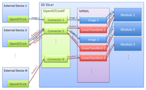
The OpenIGTLink Interface Module is a program module for network communication with external software / hardware using OpenIGTLink protocol. The module provides following features:
- Importing: The module can import position, linear transform and image data from OpenIGTLink-compliant software to the MRML scene.
- Exporting: The module can export linear transform and image data from the MRML scene to external software.
- Multi-connection: The module can manage multiple OpenIGTLink connections simultaneously.
- Locator visualization: The user can choose one of linear transforms in the MRML scene to visualize its position and orientation in the 3D space.
- Slice control: The module can control the plane to re-slice a volume image based on linear transform in the MRML scene.
Usage
Example Applications and Use Cases
- MRI-compatible Robot System (BRP Project between BWH, Johns Hopkins University and Acoustic MedSystems Inc., "Enabling Technologies for MRI-Guided Prostate Interventions")
- The 3D Slicer was connected to the MRI-compatible Robot by using OpenIGTLinkIF to send target position and to get current robot position. It was also connected to the MRI scanner to control scan plane for real-time image and receive MR images from the scanner.
- Neurosurgical Robot Project(Nagoya Institute of Technology, Japan)
- The 3D Slicer was connected to the optical tracking system (Optotrak, Northern Digital Inc.) to acquire current position of the end-effector of the robot.
Tutorial 1: Importing Tracking Data from Tracking Simulator
Step 1: Simulators
First, we prepare simulators to test connections between the 3D Slicer and external programs. The simulators come with The OpenIGTLink Library. You can also obtain the binaries from the following links:
- For Linux (x86, 32-bit).
- For Linux (x86, 64-bit).
- For Windows (32-bit).
- For Mac OS X (x86)
- For Mac OS X (PPC).
Step 2: 3D Slicer
The OpenIGTLink Interface module is included in the nightly release. The binaries can be found at Download page for Slicer Nightly Build. If you interested in building by your self, please see Build Instructions.
Step 3: Connecting the Tracker Client
Before connect the simulator to the 3D Slicer, we configure the OpenIGTLink Interface as a "server" by the following steps:
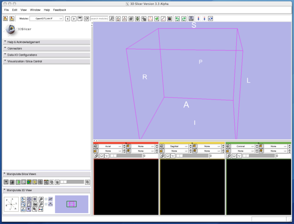
1. Select "OpenIGTLinkIF" from "Modules:" menu. The OpenIGTLink IF will show up on the 3D Slicer window.
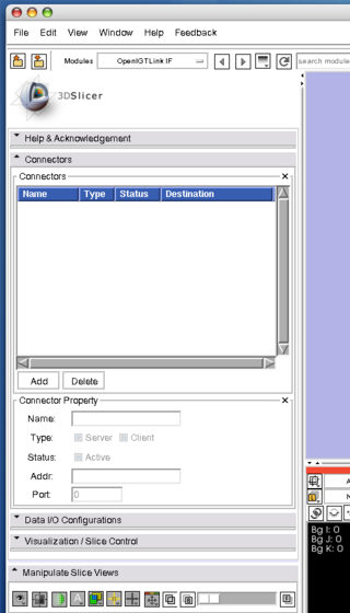
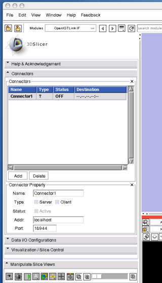
2. Open "Connectors" frame, and press "Add" button below the "Connectors" list to add a new connector
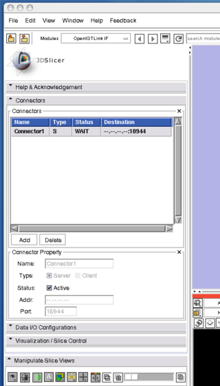
3. Once the connector is created, choose "Server" check box in the "Type" option, then clinck "Active" check box. Now the Slicer is ready to accept connections through Open IGT Link.
If the "Status" column in the connector list indicates that the connector is waiting, it is ready to connect the client program to the 3D Slicer.
Step 4: Visualizing the tracking data
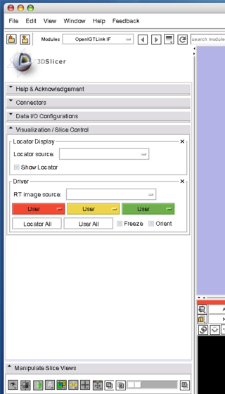
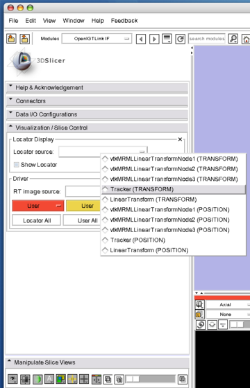
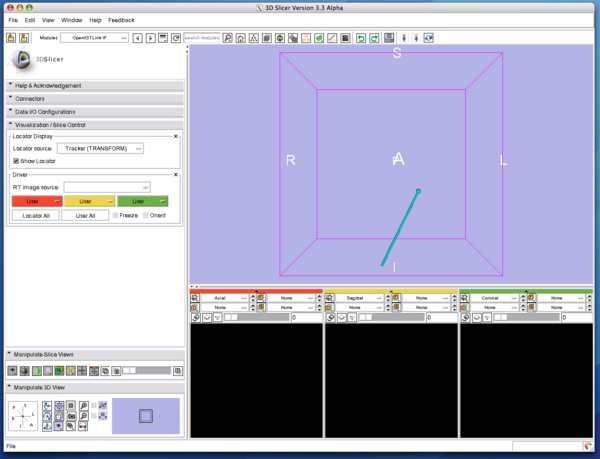
1. Open "Visualization / Slice Control", and choose "Tracker (TRANSFORM)" from "Locator Source" menu.
2. Then click "Show Locator" check button. The locator model shows up and move around in the 3D view.
Tutorial 2: Importing Image Data from Imaging Simulator
Step 1-3: Setting up 3D Slicer and simulators
Follow Step 1-3 in Tutorial 1.
Step 4: Connecting the Imager Client
To connect the tracking simulator, open a terminal (Linux and Mac) or command prompt (Windows), move to the directory containing simulator programs downloaded in Step 1, and run it. If you built the OpenIGTLink library by yourself, the binaries for the example programs (simulators) are in <OpenIGTLink-build>/bin.
$ cd <simulator directory>
To send dummy image data to the Slicer running on localhost with frame rate of 10 fps, run ImagerClieant.
$ ./ImagerClient localhost 18944 10 <sample image directory>
The sample images comes with the simulator program. If you build the OpenIGTLink library, the sample images are located in <source directory>/Examples/Imager/img/. If you are using binary version of the simulator, the sample images are in "img/" directory.
As we have seen in Tutorial 1, the "Status" column indicates "ON", if the client program connects to the 3D Slicer. If the image data is correctly received, "IMAGE" data shows up in the Data I/O Configuration tree (in the Data I/O configuration tab).
Step 5: Visualize the received image
Once the image is successfully imported to MRML, you can display it in the 2D and 3D viewers.
Tutorial 3: Exporting Tracking Data To External Software
Step 1-3: Setting up 3D Slicer and simulators
Follow Step 1-3 in Tutorial 1.
Step 4: Configure 3D Slicer as a server
Open "Connector" frame, create a connector, choose "server", configure the port number and set "Active". The Slicer is now waiting for a connection from the client. In this tutorial, the port number is supposed to be 18944.
Step 5: Connecting the Receiving Client
To connect the Receiving Client simulator, open a terminal (Linux and Mac) or command prompt (Windows), move to the directory containing simulator programs downloaded in Step 1, and run the program. If you built the OpenIGTLink library by yourself, the binaries for the example programs (simulators) are located in <OpenIGTLink-build>/bin.
$ cd <simulator directory>
To connect the Receiving Client simulator to the 3D Slicer, run ReceiveClient program with following options:
$ ./ReceiveClient localhost 18944
Once the client connects to the 3D Slicer, it starts to wait for messages from the 3D Slicer.
Step 6: Choosing MRML nodes to export
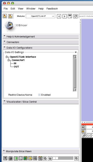
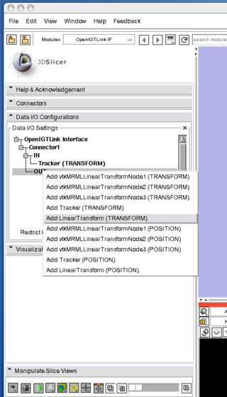
1. Open "Data I/O Configuration" frame and right click the "OUT" branch on the connector.
2. When the context menu appears, select a MRML node to export and click it.
3. You may add more nodes, by repeating 1-2.
4. The data in the nodes is exported through the OpenIGTLink connection, when ever the nodes that you have chosen is modified.
Quick Tour of Features and Use
- Connectors:
- Connector panel is used to add, delete and edit connectors.
- Data I/O Configurations:
- Visualization / Slice Control:
Development
Dependencies
The OpenIGTLink IF module requires The OpenIGTLink Library. Slicer3/Script/getbuildtest.tcl downloads and builds it in Slicer3-lib directory automatically.
Known bugs
Follow this link to the Slicer3 bug tracker.
Usability issues
Follow this link to the Slicer3 bug tracker. Please select the usability issue category when browsing or contributing.
Source code & documentation
Customize following links for your module.
Links to documentation generated by doxygen.
More Information
Acknowledgment
This work is supported by 1R01CA111288, 5U41RR019703, 5P01CA067165, 1R01CA124377, 5P41RR013218, 5U54EB005149, 5R01CA109246 from NIH. Its contents are solely the responsibility of the authors and do not necessarily represent the official views of the NIH.
References
In review ...


