Documentation/4.5/Modules/PathExplorer
|
For the latest Slicer documentation, visit the read-the-docs. |
Introduction and Acknowledgements
|
This work is supported by NA-MIC, NCIGT, and the Slicer Community. | |||||||
This project is supported by National Institute of Health (5P01CA067165, 5R01CA124377, 5R01CA138586, 2R44DE019322, 7R01CA124377, 5R42CA137886, 8P41EB015898). |
Module Description
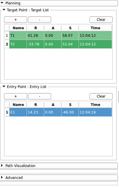
PathExplorer is a Slicer4 module, part of the SlicerIGT extension, designed to facilitate the creation of trajectory. User is able to place some target points and entry points, represented respectively by green and blue fiducials. When one target point and one entry point are selected, user can create a path that connects these two points, using a slicer ruler. Points (target and entry) could be moved in real-time, using a drag-and-drop on the fiducial, or by specifying coordinates in the entry of the table corresponding to the point to move. Selecting a trajectory in the list will automatically select in the target and entry tables the corresponding fiducials. Trajectory could be changed at this time by selecting a new target or entry point, and clicking on "Update" button.
Use Cases
PathExplorer is an interesting tool for needle insertion planning. By defining targets, and entry points, we could evaluate distance between both points, visualize the regions the needle will go through to reach the target. It is also possible to easily evaluate several entry points for a given target to find the most suitable. PathExplorer is interesting in the fact that it allows the user to reslice along the trajectory line, or perpendicular to the line. In the first case, slice plane rotate around the trajectory, in the second case, slice plane is centered on the trajectory and can 'travel' along the line. Use cases of this feature are needle insertion planning for example, to visualize path of the needle and ensure no important structures will be damaged.
Tutorials
N/A
Panels and their use
- Planning Panel
- Target table
- "+" button allows the user to place a new target point by clicking at desired location on 2D or 3D viewers.
- "-" button remove the selected line
- "Clear" button remove all points in the table
- Entry table
- Same as target table, for entry points
- Target table
- Path Creation Panel
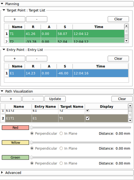
- Select a target and an entry point
- Click "+" in Path Visualization panel to create a new trajectory
- Visualization Panel
- Select a trajectory
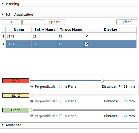
- Click on "Red" to reslice Red viewer with selected trajectory (same for Green and Yellow)
- Text of the button represent the current trajectory reslicing corresponding viewer (e.g. E1T1 reslicing red viewer, E1T2 reslicing yellow viewer, no reslicing for green viewer)
- When selecting a new trajectory previous reslicing values are automatically reloaded
- Choose perpendicular to reslice perpendicular to trajectory, In plane to reslice along the trajectory
- If reslicing perpendicularly, "Distance" value represent distance of the reslicing plane from entry point
- If reslicing in plane, "Angle" represent the angle value of the slice plane from original orientation
Similar Modules
N/A
References
Information for Developers
| Section under construction. |


