Documentation/4.5/Extensions/ResampleDTIlogEuclidean
|
For the latest Slicer documentation, visit the read-the-docs. |
Introduction and Acknowledgements
|
Extension: ResampleDTIlogEuclidean | |||||||
|
Module Description
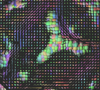
ResampleDTIlogEuclidean resamples Diffusion Tensor Images (DTI) in the log-euclidean framework. It is an improved version of ResampleDTIVolume performing the resampling in the log-euclidean space [1]. The Diffusion Tensor images transformation classes are based on algorithms described by D.C. Alexander et al [2]. More information is available in the Insight Journal
Use Cases
Tutorials
Panels and their use
Quick Tour of Features and Use
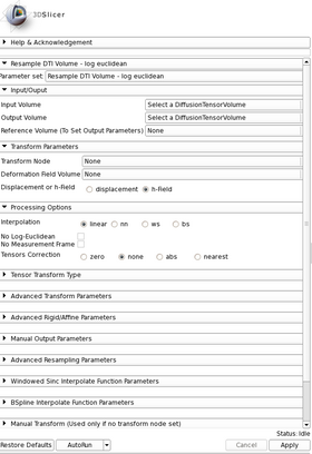
- Input/Output: Defines input and output files.
- Input volume is the volume to resample,
- Reference Volume (optional) is the volume used to set the sampling parameters (origin, spacing, orientation and dimensions). If it is not set, the input volume will be taken for reference.
- Output volume is the name of the output.
- Deformation Field: Allows the user to transform the input image using a deformation field. The deformation field is applied last in the case other transforms are given.
- Displacement or H- field sets the type of deformation field. An H-field contains at each voxel the position in space of the transformed point. The displacement field contains at each voxel the displacement vector to apply to this point.
- Deformation Field Volume sets the deformation field. It should be a 3-Dimensional vector image. Vectors should be of dimension 3.
- Resampling Parameters:
- Number Of Threads sets the number of threads used to perform the resampling.
- Correction sets if a filter is applied on the resampled image to ensure that every tensor is positive definite symmetric. Three filters are available: set to zero the negative eigen values, take their absolute values or compute their closest positive definite symmetric matrix.
- Transform Parameters:
- Transform Node contains the transform(s) to apply to the image
- Transforms Order allows the user to tell the module in what order the transforms are stored in the node (or file). Transforms should be backward (from output space to input space). However, in Slicer3, the affine and rigid transform nodes are stored as forward transforms and are inverted when passed to the module.
Input Image <- Transform0 <- Transform1 <- ... <- Transform n <- Output Image (input-to-output)
Input Image <- Transform n <- Transform n-1 <- ... <- Transform0 <- Output Image (output-to-input)
- Manual Transform: if no tranform is set in previous panel, one can enter his own transform
- Transform Matrix: a 12-parameter affine transformation manually. The first 9 numbers represent a linear transformation matrix in column-major order (where the column index varies the fastest), the last 3 are a translation.
- Transform: forces the transform to be of rigid or affine type (affine is default)
- Space: It should normally not be modified when using this module directly in Slicer3 with a transform node. It does not specify whether the matrix is expressed in LPS or RAS coordinate space but rather if everything is expressed in the same coordinate space. LPS means that everything is in the same space and RAS means that it is not the case. This option can be set to RAS if the given transform is in RAS coordinate space (respectively LPS) and the input volume is in LPS coordinate space (respectively RAS). Be careful: When passing manually the transform, the coordinate space modification is directly applied on the given transform. However, when passing the transform through a file or a transform node, it is the input volume coordinate space that is modified and the transform is left unchanged (so that any kind of transform supported by ITK is also supported by this module). If one sets the output volume parameters manually, one has to pay attention to the fact that in that case the given parameters are considered to be in the transform coordinate space!!!
- Rigid/Affine Parameters:
- Rotation Point: uses a fiducial to set a point around which the rotation defined in the transform needs to be performed.
- Centered Transform: sets the center of the transformation to the center of the image.
- Inverse ITK Transformation: inverses the transformation before applying it to the image. The transform given to the module is from the output image to the input one. If one wants to specify a transform from the input image to the output image, one should use this flag. This option can only be used if the transform is rigid or affine. Be careful: if the file containing the transform contains multiple transforms, only rigid and affine transforms will be inverted.
- Affine Transformation Type: Uses the Preservation of the Principal Direction (right image) to compute the affine transform. Otherwise, the Finite Strain Method (left image) is used [1] .
- Interpolation Type: sets the type of interpolation kernel to either linear, nearest neighbor (nn), windowed sinc (ws), or b-spline (bs). The windowed sinc interpolator uses a constant boundary condition whereas the b-spline interpolator uses a mirror boundary condition.
- Windowed Sinc Interpolate Function Parameters: selects the type window function for the sinc interpolation h=hamming, c=cosine, w=welch, l=lanczos, b=blackman. This is only relevant if one selects ws as the interpolation type.
- BSpline Interpolate Function Parameters: The spline order (only relevant if the selected interpolator is bs).
- Output Parameters: One can overwrite the reference volume parameters by setting manually the spacing, size, origin (as a fiducial), and direction matrix (also known as space directions) in column-major order.
Similar Modules
References
- [1] Arsigny, V., Fillard, P., Pennec, X. and Ayache, N. (2006), Log-Euclidean metrics for fast and simple calculus on diffusion tensors. Magn Reson Med, 56: 411–421. doi: 10.1002/mrm.20965
- [2] D.C. Alexander, C. Pierpaoli, P.J. Basser, J.C. Gee. Spatial Transformations of Diffusion Tensor Magnetic Resonance Images, IEEE Transactions on medical imaging, vol. 20, No. 11, November 2001
Information for Developers
The source code of ResampleDTIlogEuclidean is available on GitHub. It is published under an Apache License v2.0.
