Documentation/4.3/Modules/LineMarkerRegistration
|
For the latest Slicer documentation, visit the read-the-docs. |
Introduction and Acknowledgements
|
This work is part of the National Center for Image Guided Therapy (NCIGT) (P41 EB015898), National Alliance for Medical Image Computing (NA-MIC) (U54 EB005149), and other research grants (R01 CA111288, R01 CA138586) funded by National Institutes of Health and CIMIT. | |||
|
Module Description
The Line Marker Registration CLI automatically detects a fiducial marker consisting of multiple lines on a 3D image and register the marker to the image coordinate system. The users can configure the CLI to use their own fiducial marker design by creating a marker configuration file formatted in CSV.
Use Cases
Example applications of this modules:
- CT-guided percutaneous intervention (biopsy/RF ablation/cryo etc): Registration of a needle holder to the CT image coordinate system
- MRI-compatible manipulator for needle placement: Registration of the manipulator to the MRI image coordinate system
Tutorials
Installation
Currently this CLI is not available in Slicer Extension. Please obtain the source code from Git repository and build it by following the instruction.
Example Data
Example fiducial marker data (MR-visible z-frame) must be downloaded.
File:Documentation Nightly Modules LineMarkerRegistration Example.zip.
The file is zip-archived. It includes:
- zframe-config.csv (Example fiducial marker configuration file)
- zframe-image.nrrd (MR image of example fiducial marker)
- zframe-model.vtk (VTK model of fiducial marker)
Step by step instruction
First, load the MR image and the VTK model to the Scene.
You will see the model and the image in the 2D/3D viewer.
From the Modules menu, go to "IGT" > "LineMarkerRegistration. The panel of the CLI looks:
Select input volume, marker configuration file, output volume (where the result of marker segmentation is stored) and marker transform from IO menu as follows:
- Input Volume: "zframe-image"
- Marker Config File: Click the button next to the text input, and choose "zframe-config.csv" which is in the Examples folder in the source.
- Output Volume: Choose "Create new Volume" to create a new scalar volume node.
- Marker Volume: Choose "Create new LinearTransform" to create a new linear transform node. (The name will be "Marker transform".)
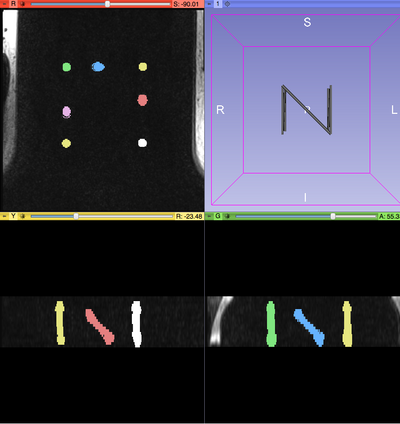
Leave other parameters as they are (the default values are adjusted for the example data). Now you can click the "Apply" button to run the CLI. It usually takes 2-10 seconds to complete. If it is successful, you could see the segmented line markers on the 2D viewers as below:
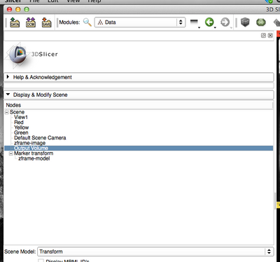
To confirm that the line marker is registered to the image, you need to apply the marker transform to the Z-frame model. To do this, open the "Data" module and drag the "zframe-model" node to the "Marker transform".
By clicking the "eye" icon on the red slice, you could show the axial image and the model in the 3D viewer at the same time. Move the slice with the slider in the 2D viewer and check if the model is well overlapped with the segmented marker.
Panels and their use
N/A
Similar Modules
N/A
References
N/A
Information for Developers
| Section under construction. |


