Documentation/4.8/Modules/AnglePlanes

From Slicer Wiki
Revision as of 07:06, 18 October 2017 by UpdateBot (talk | contribs) (Nightly -> 4.8)
(diff) ← Older revision | Latest revision (diff) | Newer revision → (diff)
Jump to: navigation, search
Home < Documentation < 4.8 < Modules < AnglePlanes


For the latest Slicer documentation, visit the read-the-docs.


Introduction and Acknowledgements

Extension: ShapeQuantifier
Acknowledgments: This work was supported by the National Institues of Dental and Craniofacial Research and Biomedical Imaging and Bioengineering of the National Institutes of Health under Award Number R01DE024450
Author: Julia Lopinto, University of Michigan
Contributors:
- Francois Budin (NIRAL, University of North Carolina),
- Beatriz Paniagua (NIRAL, University of North Carolina),
- Lucia Cevidanes (University of Michigan - School of Dentistry)
- Jean-Baptiste Vimort (University of Michigan - School of Dentistry)
Contact: Jean-Baptiste Vimort, <email>jb.vimort@gmail.com</email>
License: Apache License, Version 2.0

Extension Description

This Module is used to calculate the angle between two plans by using the normals. The user gets the choice to use two plans which are already implemented on Slicer or they can define a plan by using landmarks (at least 3 landmarks). Plans can also be saved to be reused for other models.

Interface

Logo for AnglePlanes
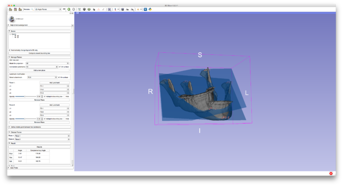
User Interface of AnglePlanes
AnglePlanes in Slicer

Tutorials

Scene

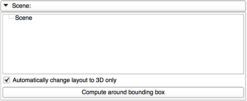
CMFSceneTab.png This tab allows the user to display and hide all the models contained in Slicer's scene.

There is an option to automatically set the view in Slicer to 3D only each time that the user is using this module.
The "compute around bounding box" button will adjust the bounding box around all the displayed models in Slicer.

Manage plans

  • Create a plan:
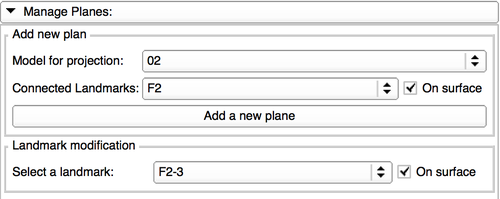
CMFMangePlaneTab1.png To create a plan, the user will need to select a model (on which each landmark will be projected) and a list of landmarks.

This list of Landmarks can already contain landmarks, if that is the case the "on surface" option will project all the landmarks that are not defined as a middle point.
Only one landmark can be moved at the time, the one that is selected in the "landmark modification" part. This landmark can be kept on the surface or not.

  • Modify a plan:
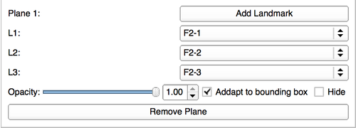
CMFMangePlaneTab2.png Once the plan created, there is a possibility to add landmarks to the list.

Each plan will be defined by three different landmarks.
There is also some options to select the opacity of each plan, hide it, or adapt it to the bounding box.
The remove plan option will erase the plan from Angle Plans, but the landmarks list will remain intact.

Define a middle point

CMFDefineMiddlePointTab.png In this tab, the user will have to define a middle point defined with two landmarks from the same list.

Angle plan won't allow the modification of any middle point, therefore all the middle points will be updated when one of the landmarks that define its is moved.

Choose plans

CMFChoosePlanesTab.png This tab is fore the selection of the two plans that will be used for the measurement, the user can also choose two use one of the three fundamental plans.

Results

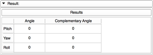
CMFResultsTab.png The result tab will display the Pitch, Yaw and Roll between the to plans selected in the previous tab.

Save

CMFSaveTab.png The positions of the red, green and yellow plans can be saved and reloaded thanks to this tab.

Similar Extensions

N/A

Information for Developers

The source code is available on