Documentation/4.6/Registration/RegistrationLibrary/RegLib C29
|
For the latest Slicer documentation, visit the read-the-docs. |
Contents
Slicer Registration Library Case #29: Intra-subject Brain DTI
Input

|

|

|

|

|
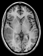
| moving image T1 SPGR |
fixed image 1 T2 |
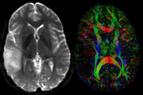
moving image DTI baseline+DTI tensor |
Description
This is a classic case of a multi-sequence MRI exam we wish to spatially align to the anatomical reference scan (T1-SPGR). The scan of interest is the DTI image to be aligned for surgical planning/reference. Unlike Case 27 this one does contain both a T1 and a T2 image. The T2 image being closer in contrast to the DWI/DTI baseline, it makes for the better registration reference. However the T1 contains the tissue contrast of interest.
Approach: we can use either T1 or T2 as the spatial reference. Ultimately we seek to overlay the DTI information onto the T1 image. But the T2 makes for a better registration reference because it matches better the DTI baseline contrast. Hence we will use the T2 as the reference and align the T1 to the T2 in a separate registration step. The typical DTI challenges are present here also:
- The DWI sequence (EPI) contains distortions we seek to correct via non-rigid alignment
- The DWI sequence also contains intensity inhomogeneity (coil bias)
- the DTI baseline is similar in contrast to a T2, albeit at much lower resolution
- we have different amounts of voxel-anisotropy
Modules used
- DiffusionWeightedVolumeMasking
- Diffusion Tensor Estimation
- Editor (for mask generation)
- General Registration (BRAINS)
- Resample DTI Volume
Download (from NAMIC MIDAS)
Why 2 sets of files? The "input data" mrb includes only the unregistered data to try the method yourself from start to finish. The full dataset includes intermediate files and results (transforms, resampled images etc.). If you use the full dataset we recommend to choose different names for the images/results you create yourself to distinguish the old data from the new one you generated yourself.
- RegLib_C29_raw.mrb (input data, Slicer mrb file. 71 MB).
- RegLib_C29_full.mrb (input data+results, Slicer mrb file. 124 MB).
Keywords
MRI, brain, head, intra-subject, DTI, T1, T2, non-rigid, tumor, surgical planning
Registration Approach
- a direct registration of the DTI_baseline to the T1 is not recommended, since the T2 is a better match in contrast to the DTI baseline. We therefore first align the DTI with the T2 and then also register the T1 to the T2.
- the DTI-T2 registration includes non-rigid deformation to correct for the strong distortions from the EPI acquisition. Because of the nonrigid component a mask of the brain parenchyma helps in obtaining a meaningful transform. Registration without a mask is possible but not as good as with a mask.
- The DTI estimation provides an automated mask for the DTI_baseline scan, but we have no mask for the T2. We obtain a T2 mask through separate segmentation.
- thus the suggested pipeline is:
- convert the DWI to DTI and generate a mask + baseline image
- build a mask for the T2
- Register DTI_baseline to T2
- Resample DTI with the result transform
- Register T1 to T2
Video Screencasts
- Phase 1: Converting DWI to a DTI image
- Phase 2:Building a Mask for the T2 (See here for a selection of videos showing 6 different methods to build a mask)
- Phase 3:Register DTI baseline to T2 (with dilated mask)
- Phase 4:Resample DTI into space of T2
- Phase 5:Register T1 to T2
Procedures
- Phase 1a: Preprocessing: Build DWI mask + baseline
- open the DiffusionWeightedVolumeMasking module
- Input DWI Volume: "DWI"
- Output Baseline Volume: Create & Rename New Volume, rename to "DWI_baseline"
- Output Threshold Mask: Create & Rename New Volume, rename to "DWI_mask"
- Leave other settings at default; click Apply -> You should obtain a baseline scalar image and a mask label map.
- Phase 1b: Preprocessing: Convert DWI -> DTI
- open the Diffusion Tensor Estimation module
- Input DWI Volume: DWI
- Output DTI Volume: create & rename new, rename to "DTI"
- Output Baseline Volume: create & rename new, rename to "DTI_baseline"
- Click: Apply -> you should get a 3x3 tensor image + a baseline image with contrast similar to a T2
- Phase 2: build a T2 mask
See here for a selection of videos showing 6 different methods to build a mask. Below is one of those, using the "GrowCut" tool in the Editor
- Open the "Editor" module , select the T2 as master volume and create a new label map.
- select the brush tool, set the label to 2 and the brush size to 80 mm or larger (filling almost entire FOV)
- on 4 or 5 slices select the entire head and a good portion of the background
- switch to the Level Tracing effect/tool. Switch the label to 1.
- On the same slices as before, place the cursor near the brain surface until the yellow outline shows a good enclosure of the brain at that slice. Click the left mouse to fill.
- you should now have a handful of slices, even distributed, where label 1 describes the brain parenchyma and label 2 everything else.
- switch to the GrowCutEffect and click Apply.
- Apply some Dilation filtering: we want the mask to include the brain surface. Select the Dilation Effect and apply 3-4 times to grow the edge of the mask outward.
- Also dilate the DWI mask:' switch to the DWI_mask image and also apply 3-4 steps of dilation
- Phase 3: Register DTI (masked)
- open the General Registration (BRAINS) module
- Fixed Image Volume: T2
- Moving Image Volume: DTI_baseline
- Output Settings:
- Slicer BSpline Transform": create & rename new transform, rename to "Xf1_DTI-T1"
- Slicer Linear Transform: none
- Output Image Volume: create new volume, rename to DTI_baseline_Xf1
- Registration Phases: check boxes for Rigid, Rigid+Scale, Affine and BSpline
- Main Parameters:
- Number Of Samples: 500,000
- B-Spline Grid Size: 7,7,5
- Mask Option: select ROI button
- (ROI) masking input fixed: DWI_mask
- (ROI) masking input moving: T2_mask
- Leave all other settings at default
- click: Apply. This may take several minutes depending on your CPU.
- Phase 4: Resample DTI
- Open the Resample DTI Volume module] (under All Modules menu; note this is distinct from the ResampleScalarVectorDWIVolume used above)
- Input Volume: DTI
- Output Volume: create new DTI Volume, rename to DTI_Xf2
- Reference Volume: T2_Xf1
- Transform Node: select "Xf2_DTI-T1" created above
- check box: displacement
- leave all other settings at defaults
- Click Apply; runtime ~ 3 min.
- set T1 or FLAIR as background and the new DTI_Xf2 volume as foreground
- Move fade slider to see DTI overlay onto the structural image
- Phase 5: register T2 to T1
- open the General Registration (BRAINS) module
- Fixed Image Volume: T1
- Moving Image Volume: T2
- Output Settings:
- Slicer BSpline Transform": none
- Slicer Linear Transform: create & rename new transform, rename to "Xf3_T1-T2"
- Output Image Volume: none (since this is an affine transform we need not resample to see the result)
- Registration Phases: check boxes for Rigid and Affine
- Main Parameters : Number Of Samples: 200,000
- Leave all other settings at default
- click: Apply; runtime < 10 sec (MacPro QuadCore 2.4GHz) -> This only generates the transform. We still need to apply it to the image
- Go to the Data module. Find the nodes/entries for the T1 and the Xf3_T1-T2 transform. Drag the T1 node onto/into the transform Xf3_T2-T1 node. You should see the T2 now being listed nested within the transform.
- right-click on the T1 image and from the pop-up menu, select Harden Transform. This will apply the transform and move the new T1 back out onto the main level
- double click on the T1 node and rename it to "T1_Xf3" or similar to make a record that this is no longer the original T1. Note that when you save your result, the save dialog may still display the name of the original T1. Make sure to change that before saving to prevent overwriting the original. Note that this way of applying the transform avoids resampling the data, it merely places the new orientation as a matrix in the image header.
- Save results.
Registration Results
 |
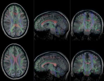
original and registered pair of T1 and DTI (click to enlarge) |