Documentation/4.8/Modules/GeodesicSlicer
|
For the latest Slicer documentation, visit the read-the-docs. |
Introduction and Acknowledgements
|
The module has been developed based on ideas and feedbacks from the community. We would like to especially thank:
- Dr. Olivier Etard, M.D., Ph.D., CHU de Caen.
- Dr. Clément Nathou, M.D., Ph.D., CHU de Caen.
- Dr. Sonia Dollfus, M.D., Ph.D., CHU de Caen, header of ISTS.
- Dr. Csaba Pinter, MSc, Queen's University.
- Dr. Andras Lasso, Ph.D., Queen's University.
If you use this module, please cite the following article: [1].
Contents
Module Description
This module calculates geodesic path in 3D structure. Thanks to this geodesic path, this module can draw an EEG 10-20 system, determine the projected scalp stimulation site (MRI guided brain stimulation without the use of a neuronavigation System) and correct the rTMS resting motor threshold by correction factor.
Terminology
- Mesh A mesh or polygon mesh is a collection of vertices, edges and faces that defines the shape of a polyhedral object in 3D computer graphics and solid modeling.
- Shortest path In graph theory, the shortest path problem is the problem of finding a path between two vertices (or nodes) in a graph such that the sum of the weights of its constituent edges is minimized.
- 10-20 EEG system The International 10-20 system is commonly used for electroencephalogram (EEG) electrode placement and to correlate external skull locations with underlying cortical areas.[2]
Use Cases
The overall goal is to allow users to find the shortest paths between nodes in a graph and via the Dijkstra's algorithm to make 10-20 system. This module can be used for:
- Stimulation in psychiatry: MRI guided brain stimulation without the use of a neuronavigation system.
- Surgery measurement.
- 3D printing.
Panels and their use
Create a mesh
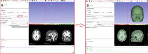
A typical straightforward Geodesic Slicer workflow for consists of the following steps:
- Load a volume.nii.
- Enter in the Geodesic Slicer module using either the toolbar or the Modules menu button.
- Press the button "Create a mesh".
- Wait a moment.
- If the segmentation is fine, press the button "Use this mesh".
- If your image was named 'T1.nii' the output will be called 'T1.stl', in the same directory of your initial image.
- Go to Parameters to find the shortest path or Make 10-20 EEG system electrode section.
Parameters to find the shortest path
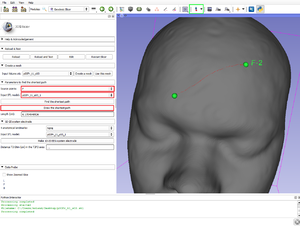
- Source points: The list of fiducial points on the curve, since the "Create-and-place Fiducial" button (in green in the figure above).
- Input STL model: The model you use (after "use this mesh", the T1.stl created).
- Find the shortest path: Calculate in centimeter the geodesic (shortest) path via the Dijkstra's algorithm.
- Draw the shortest path: Draw the Dijkstra's algorithm shortest path.
- Length (cm): The length of the current curve is shown in centimeter.
10-20 system electrode
- Run the Dijkstra's algorithm to make the 10-20 system electrode.
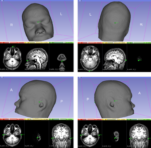
- 4 anatomical landmarks: (Sources Points) The list of fiducial points on the curve, since the "Create-and-place Fiducial" button (in green in the figure above). Four anatomical landmarks are used for the essential positioning of the electrodes (in this order!):
- 1/ The nasion
- 2/ The inion
- 3/ The pre auricular to the left ear
- 4/ The pre auricular to the right ear
- Input STL model: The model you use (after "use this mesh", the T1.stl created).
- Press the button "Make 10-20 EEG system electrode" to draw the 10-20 EEG system via the Dijkstra's algorithm.
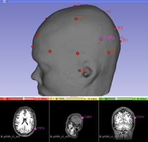
- The traditional T3P3 site according to the International 10–20 system of electroencephalogram was identified.
- Project the stimulation site on the 10-20 system electrode distances and characterize it.
- Stimulation Site placed: Place on the T1-weighted anatomical image the stimulation point that you want since the "Create-and-place Fiducial" button. Once this point given, click on 'Yes'.
- Press the button "Project the stimulation site" to project the stimulation point on the scalp and find the 3nearest electrodes around it.
- Nearest electrode 1: The distance in centimeter between the first nearest electrode and the projected stimulation site.
- Nearest electrode 2: The distance in centimeter between the second nearest electrode and the projected stimulation site.
- Nearest electrode 3: The distance in centimeter between the third nearest electrode and the projected stimulation site.
rTMS resting motor threshold- Correction factor
Calculate correction factors to adjust the rTMS dose for the treatment (according to the depth of the stimulation site).
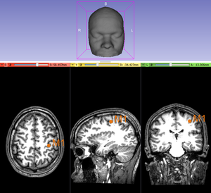
- M1 Point Placed: Place on the T1-weighted anatomical image a point targeting the human motor cortex since the "Create-and-place Fiducial" button. Once this point given, click on 'Yes'. Help via the Yousry's method.
- Set the stimulation intensity of the resting motor threshold.
- Press the button "Correct the motor threshold" to correct the unadjusted motor threshold (rMT) in % stimulator output.
- Two adjusted motor threshold (AdjMT%) in % stimulator output are given where SCDx is the scalp-to-cortex distance between the scalp and and the Stimulation Site, SCDm is the scalp-to-cortex distance between the scalp and M1.
- 1/ The first according to Stokes et al. Clin Neurophysiol 2007 [3] , where [AdjMT% = 2,7 x (SCDx - SCDm) + rMT]
- 2/ The second according to Hoffman et al. Biol Psychiatry 2013 [4] , where [AdjMT% = 0.90*rMT*e0.036*(SCDt-SCDm)]
Information for Developers
The code is available at Github.
References
- ↑ Briend F. et al., Personalized or standardized target for the treatment of auditory hallucinations by rTMS? Biological Psychiatry, submitted
- ↑ Jasper, H. (1958). The ten twenty electrode system of the international federation. Electroencephalography and Clinical Neurophysiology, 10, 371‑375.
- ↑ Stokes, M. G., Chambers, C. D., Gould, I. C., English, T., McNaught, E., McDonald, O., & Mattingley, J. B. (2007). Distance-adjusted motor threshold for transcranial magnetic stimulation. Clinical Neurophysiology, 118(7), 1617‑1625.
- ↑ Hoffman, R. E., Wu, K., Pittman, B., Cahill, J. D., Hawkins, K. A., Fernandez, T., & Hannestad, J. (2013). Transcranial magnetic stimulation of Wernicke’s and Right homologous sites to curtail « voices »: a randomized trial. Biological Psychiatry, 73(10), 1008‑1014.
