Modules:EMSegmenter-3.6
Return to Slicer 3.6 Documentation
EMSegmenter
EMSegmenter

|
General Information
Module Type & Category
Type: Interactive
Category: Segmentation
Authors, Collaborators & Contact
- Brad Davis, Kitware
- Kilian Pohl: IBM
- Contact: Kilian Pohl <pohl@csail.mit.edu>
Module Description
This module is designed for users who perform atlas based medical image segmentation. The module can be operataded in two modes: an advance mode that allows users to parameterization the tool to specific segmentation tasks and a simple mode which is designed for users who would like to apply the parameterization to new data with a minimal amount of user interaction. One can also apply the parameterization to medical scans via the command-line EMSegment executable. The remainder of this sections describes the work flow of the two modes in further detail:
Usage
The purpose of the module is to configure the algorithm to automatically segment anatomical structures in medical images. First the user has to specify parameters defining the image protocol and the anatomical structures of interests. This process results in a template that the module uses to automatically segment large data sets. The template is composed of atlas data and a non-trivial collection of parameters for the EMSegment algorithm.
Once the parameters are specified, the target images are segmented using the EM Segmentation algorithm (Pohl et al. TMI 2007). If the results are satisfactory, the template is saved and can be used later to segment new images (via the GUI or batch processing). If the results are unsatisfactory, the parameters can be modified and the segmentation re-run.
One important aspect of the project is the workflow wizard. This wizard simplifies the module by dividing the complicated template specification task into a number of smaller, intuitive steps.
Advanced Mode
The work flow is defined by nine steps which one can navigate via the "Back", "Next", or "Segment" button. The Segment button jumps right away to the last step of the work flow and segments the medical scans into the structures of interests.
Step 1: Define Task
Select an already existing task or define a new one. Click on the "Advanced Button" in the pop up window. A MRML file defining parameters of the algorithm specific to the task as well atlas data are automatically downloaded for existing Tasks.
Step 2: Define Input Channel
Define the number of input channels as well as the name of each channel and the corresponding scan associated with the channel. If the scans are not aligned with each other click on "Align input scans"
Step 3: Define Anatomical Tree
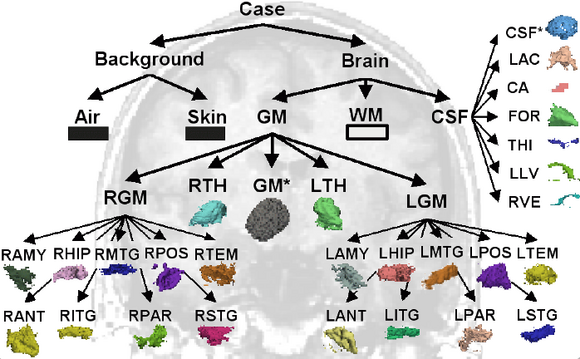
The user specifies the hierarchical relationship between the anatomical structures. The tree will refine the complex segmentation task into a set of easier segmentation problems. A sub-classes is added to an existing structure by right-clicking on the structure and selecting "Add sub-structure". The name, label, and color of a structure are modified by selecting the structure in the tree and then defining these attributes in the panel below.
Step 4: Define Atlas
In this step, the user links the probabilistic atlases to the anatomical structures in the tree by first highlighting the structure and then selecting the volume representing the probability map of that structure in the panel below. We note that the probabilistic atlas of structures with substructures is defined by the atlases of the substructures and thus is note explicitly defined.
Step 5: Edit Registration Parameters
The atlas is in general not aligned to the specific patient scans defined in Step 1. The user specifies in this step the scans of the atlas corresponding to the input channels in Step 1 as well as the type of registration (Affine / non-rigid) and the interpolation.
Step 6: Define Preprocessing
This step is defined via task specific Tcl file that configures the preprocessing pipeline of the input scans and the atlas. Complete the step by going through the task specific check list, clicking on the next button, and clicking on the yes button of the pop up window. One can define a new preprocessing pipeline by specifying the pipeline via Tcl file, placing the file in Slicer3-build/share/Slicer3/Modules/EMSegment/Tasks and listing the file name in the task specific MRML file.
Step 7: Specify Intensity Distribution
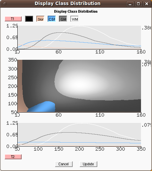
Refining the intensity distribution for each structure of interest is often a critical step in the parameterization of the segmentation algorithm. Slicer 3.6 includes an overview window that show the distribution in a 1D and 2D graph (press "Plot Distributions" to view the graph). By placing the mouse cursor of the 2D viewers the corresponding intensity value is shown in the graph.
Step 8: Edit Node-based Parameters
Users specify the relative to weight of a node in the tree with respect to other structures which are children of the same parent node. The first tab also specifies the weight of the input channels as well as the atlases. Alpha specifies the smoothing applied to the structure (via MRFs). The second tab (Stopping Condition) lists the number of iterations associated with the segmentation task. By default , the Bias iteration is set to -1 which means that it is performed each iteration. If the value is greater -1 then the inhomogeneity computation is stopped after n iterations. The third tab specifies printing out intermediate results, which are saved in the working directory specified in the next step
Step 9: Run Segmentation
This panels lists the general parameters necessary for segmenting images. Users can specify a region of interest to speed up the segmentation algorithm. Pressing the Segment button creates a label map of the anatomical structures.
Simple Mode
Unlike the Advanced mode, the simple mode only consists of two steps. The first step is exactly like previously described in the Advanced mode. By pressing the "Simple" button the work flow advance to the only other step, where the user specifies the scans to be segmented as well as the check list associated with the preprocessing.
Use Cases, Examples & Tutorials
- A full Tutorial for all three EMSegment modules
These slides and data describe the Slicer3 implementation of all three EMSegment modules and demonstrate their use. A recent (later than 7Jan08) version of Slicer3 is required to run the test data.
Tutorial Slides - Tutorial Data
- Another detailed training tutorial on EM Segment algorithm and Slicer3 EMSegment Template Builder module
Tutorial Slides - Training Data
Quick Tour of Features and Use
There is a step-by-step instruction with screen shots to describe the Workflow Wizard interface. Here is the brief version of the steps in the wizard:
- 1/9 Define Parameters Set: Select parameter set or create new parameters
- 2/9 Define Hierarchy: Define a hierarchy of anatomical structures
- 3/9 Assign Atlas: Assign atlases for anatomical structures
- 4/9 Select Target Images: Choose the set of images that will be segmented
- 5/9 Intensity Normalization: Normalize target images
- 6/9 Specify Intensity Distributions: Define intensity distribution for each anatomical structure
- 7/9 Edit Node-based Parameters: Specify node-based segmentation parameters
- 8/9 Edit Registration Parameters: Specify atlas-to-target registration parameters
- 9/9 Run Segmentation: Save work and apply EM Algorithm to segment target images
Development
The overall design of the EMSegment module is described in the AHM2008 slides.
The module is implemented as a programmatic Slicer3 module because it requires a large degree of interaction with the user, the data stored in the MRML tree, and the Slicer3 GUI itself. Because the MRML node structure is rather complicated (for example the anatomical tissue hierarchy and a large number of interdependent nodes) the Logic class is solely responsible for maintaining and accessing these nodes. The Logic class provides an API that the GUI code uses to access and modify data. The Logic class also wraps the algorithm code itself.
Notes from the Developer(s)
N/A
Dependencies
Slicer3 base modules.
Tests
On the Dashboard, these tests verify that the module is working on various platforms:
- vtkEMSegmentBlackBoxSegmentationTest
- vtkEMSegmentMRMLManagerTest
- vtkEMSegmentPreprocessingManagerTest
- vtkEMSegmentReadWriteMRMLTest
- vtkEMSegmentTestUtilities
Known bugs
http://www.na-mic.org/Bug/view_all_bug_page.php Links ] to known bugs in the Slicer3 bug tracker. Please expand the search options, select EMSegmenter in the category, and press apply filter
Usability issues
Follow this link to the Slicer3 bug tracker. Please select the usability issue category when browsing or contributing.
Source code & documentation
Links for the module.
More Information
- Background materials: EMSegment history
- For more information about the EM Segmenter project in Slicer3 see the old EMSegment Wiki page here
- The old EMSegment FAQ contains frequently asked questions about the EMSegment interfaces in Slicer3.
- There is also an old EMSegmenter Mini-Tutorials
Acknowledgment
We thank Andriy Fedorov and Alexander Zaitsev for pointing to and fixing issues in the early development. Funding for the EMSegment module was provided by NA-MIC and NAC (PI: Ron Kikinis).
References
- Wells III W.M., Grimson W.E.L., Kikinis R., Jolesz F.A. Adaptive segmentation of MRI data. IEEE Trans Med Imaging. 1996; 15(4):429-442.
- Pohl K.M., Fisher III J.W., Grimson W.E.L., Kikinis R., Wells III W.M. A Bayesian model for joint segmentation and registration. Neuroimage. 2006 May 15;31(1):228-39.
- Pohl K, Bouix S, Nakamura M, Rohlfing T, McCarley R, Kikinis R, Grimson W, Shenton M, Wells W. A Hierarchical Algorithm for MR Brain Image Parcellation. IEEE Transactions on Medical Imaging. 2007 Sept;26(9):1201-1212. [bib]
