|
|
| Line 58: |
Line 58: |
| | | | |
| | * '''Input/Output:''' | | * '''Input/Output:''' |
| − | ** '''Labeled Image:''' The input labeled image. | + | ** '''Moving Image:''' The input moving image. |
| − | ** '''Output Mesh:''' The output tetrahedral mesh in vtk file format. (default: outputMesh.vtk) | + | ** '''Fixed Image:''' The input moving image. |
| | + | ** '''Mask Image:''' The input moving image. |
| | + | ** '''Mesh:''' The input moving image. |
| | + | ** '''Output Volume:''' Moving image to the fixed image coordinate frame (optional). |
| | + | ** '''Output Direct Deformation Field:''' Transform calculated that aligns the fixed and moving image. Maps positions in the moving coordinate frame to the fixed coordinate frame (optional). |
| | + | ** '''Output Inverse Deformation Field:''' Transform calculated that aligns the fixed and moving image. Maps positions in the fixed coordinate frame to the moving coordinate frame (optional). |
| | + | ** '''Output Warped Mesh:''' The warped tetrahedral mesh in vtk file format (optional). |
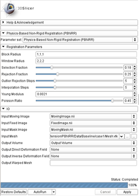
| | |[[Image:PBNRR_panel.png|thumb|280px|PBNRR UI]] | | |[[Image:PBNRR_panel.png|thumb|280px|PBNRR UI]] |
| | |} | | |} |
Revision as of 16:14, 20 June 2014
Home < Documentation < Nightly < Extensions < PBNRR
Introduction and Acknowledgements
|
Extension: Physics-Based Non-Rigid Registration (PBNRR)
Acknowledgments:
This work is funded mainly by the ARRA funds for the ITK-v4 implementation with grant number:NLMA2D2201000586P. In addition, this work is supported in part by NSFgrants:CCF-1139864, CCF-1136538, and CSI-1136536 and by the John Simon Guggenheim Foundation and the Richard T.Cheng Endowment.
Author: Fotis Drakopoulos
Contributors: Fotis Drakopoulos (CRTC), Yixun Liu (CRTC), Andriy Kot (CRTC), Andrey Fedorov (SPL B&W Harvard), Olivier Clatz (Asclepios INRIA), Nikos Chrisochoides (CRTC)
Contact: Nikos Chrisochoides, <email>npchris@gmail.com</email>
Website: https://crtc.cs.odu.edu/joomla/
License: BSD
|
| Center for Real-time Computing
|
|
|
Module Description
The module Non-Rigid Registers a moving to a fixed MRI. It uses a linear homogeneous bio-mechanical model to compute a dense deformation field that defines a transformation for every point in the fixed image to the moving image. The method includes three components (Feature Point Selection, Block Matching and Finite Element Solver) combine together to provide a user-friendly interface.
Use Cases
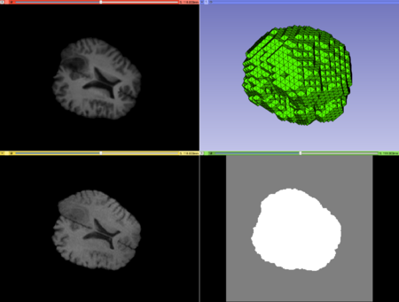 Case1 Input; top left: moving image, top right: mesh, bottom left: fixed image, bottom right: mask image. |
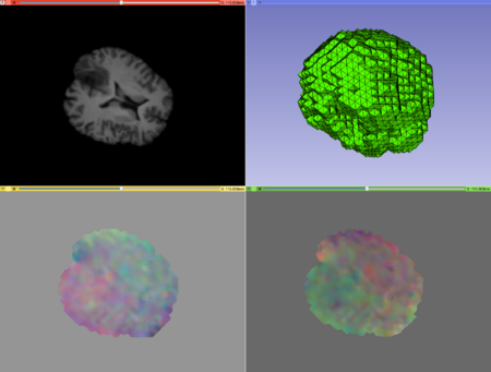 Case1 Output; top left: warped image, top right: warped mesh, bottom left: direct deformation field, bottom right: inverse deformation field. |
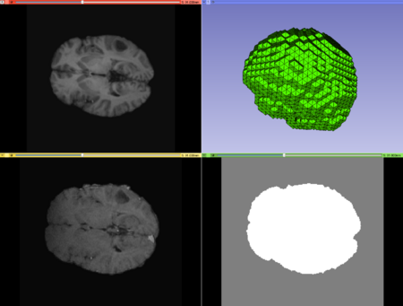 Case2 Input; top left: moving image, top right: mesh, bottom left: fixed image, bottom right: mask image. |
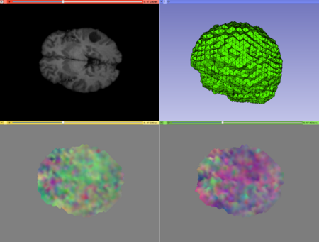 Case2 Output; top left: warped image, top right: warped mesh, bottom left: direct deformation field, bottom right: inverse deformation field. |
Tutorials
Panels and their use
- Registration Parameters:
- Block Radius: Radius (in image voxels) of the selected image blocks in each dimension (default: 1,1,1).
- Window Radius: Radius (in image voxels) of the Block Matching window in each dimension (default: 5,5,5).
- Selection Fraction: Fraction of the selected blocks from the total number of image blocks. Value should be between [0.01,1] (default: 0.05).
- Rejection Fraction: Fraction of the rejected blocks from the number of the selected image blocks. Value should be between [0.01,1) (default: 0.25).
- Outlier Rejection Steps: Number of outlier rejection steps. Value should be between [1,20] (default: 5).
- Interpolation Steps: Number of interpolation steps. Value should be between [1,20] (default: 5).
- Young Modulus: Young Modulus of the linear bio-mechanical model (default: 0.0021 N/mm2).
- Poisson Ratio: Poisson Ratio of the linear bio-mechanical model. Value should be between [0.10,0.49] (default: 0.45).
- Input/Output:
- Moving Image: The input moving image.
- Fixed Image: The input moving image.
- Mask Image: The input moving image.
- Mesh: The input moving image.
- Output Volume: Moving image to the fixed image coordinate frame (optional).
- Output Direct Deformation Field: Transform calculated that aligns the fixed and moving image. Maps positions in the moving coordinate frame to the fixed coordinate frame (optional).
- Output Inverse Deformation Field: Transform calculated that aligns the fixed and moving image. Maps positions in the fixed coordinate frame to the moving coordinate frame (optional).
- Output Warped Mesh: The warped tetrahedral mesh in vtk file format (optional).
|
|
Similar Modules
References
- Xiaodong Tao, Ming-ching Chang, “A Skull Stripping Method Using Deformable Surface and Tissue Classification”, SPIE Medical Imaging, San Diego, CA, 2010.
- Ming-ching Chang, Xiaodong Tao “Subvoxel Segmentation and Representation of Brain Cortex Using Fuzzy Clustering and Gradient Vector Diffusion”, SPIE Medical Imaging, San Diego, CA, 2010.
Information for Developers


