Difference between revisions of "Documentation/4.0/Modules/OpenIGTLinkIF"
| Line 57: | Line 57: | ||
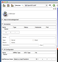
|[[Image:Slicer4-OpenIGTLinkIF-IOConfiguration.png|thumb|200px|I/O Configuration Tree interface]] | |[[Image:Slicer4-OpenIGTLinkIF-IOConfiguration.png|thumb|200px|I/O Configuration Tree interface]] | ||
|} | |} | ||
| − | |||
| − | |||
<!-- ---------------------------- --> | <!-- ---------------------------- --> | ||
Revision as of 15:08, 15 April 2012
Home < Documentation < 4.0 < Modules < OpenIGTLinkIF
Introduction and Acknowledgements
|
This work is supported by NA-MIC, NCIGT, and the Slicer Community. This work is partially supported by NIH 1R01CA111288-01A1 "Enabling Technologies for MRI-Guided Prostate Interventions" (PI: Clare Tempany), P01-CA67165 "Image Guided Therapy" (PI: Ferenc Joelsz) and AIST Intelligent Surgical Instrument Project (PI: Makoto Hashizume, Site-PI: Nobuhiko Hata). | |||||
|
Module Description
|
The OpenIGTLink Interface Module is a program module for network communication with external software / hardware using OpenIGTLink protocol. The module provides following features:
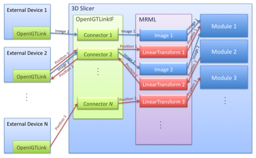
 The figure shows an example schematic diagram where multiple devices are communicating with 3D Slicer through the OpenIGTLink Interface. Each connector is assigned to one of the external devices for TCP/IP connection. The connectors serve as interfaces between the external devices and the MRML scene to convert an OpenIGTLink message to a MRML node or vice versa. |
Supported Devices
See here for a list of supported devices.
Use Cases
- MRI-compatible Robotic Systems (BRP Project between BWH, Johns Hopkins University and Acoustic MedSystems Inc., "Enabling Technologies for MRI-Guided Prostate Interventions")
- The 3D Slicer was connected to an MRI-compatible Robot, using OpenIGTLinkIF to send target position from Slicer to the robot and to send the actual robot position (based on sensor information) from the robot back to Slicer. Slicer was also connected to the MRI scanner. Scan plane position and orientation were prescribed in Slicer and transmitted to the scanner for controlling real-time image acquisition and for transferring the acquired images from the MR scanner back into Slicer for display.
- Neurosurgical Robot Project(Nagoya Institute of Technology, Japan)
- The 3D Slicer was connected to the optical tracking system (Optotrak, Northern Digital Inc.) to acquire current position of the end-effector of the robot.
Tutorials
Please follow the OpenIGTLink IF Tutorial presentation file.
Panels and their use
A list of all the panels in the interface, their features, what they mean, and how to use them.
Similar Modules
N/A
References
- Tokuda J, Fischer GS, Papademetris X, Yaniv Z, Ibanez L, Cheng P, Liu H, Blevins J, Arata J, Golby A, Kapur T, Pieper S, Burdette EC, Fichtinger G, Tempany CM, Hata N, OpenIGTLink: An Open Network Protocol for Image-Guided Therapy Environment, Int J Med Robot Comput Assist Surg, 2009 (In print)
Information for Developers
| Section under construction. |


