Difference between revisions of "Documentation/Nightly/Modules/MeshCompression"
| Line 33: | Line 33: | ||
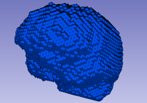
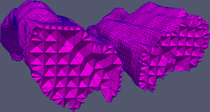
|[[File:brain_before.jpg|thumb|300px|Brain BCC mesh before MC]] | |[[File:brain_before.jpg|thumb|300px|Brain BCC mesh before MC]] | ||
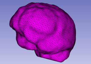
|[[File:brain_after.jpg|thumb|300px|Brain BCC mesh after MC]] | |[[File:brain_after.jpg|thumb|300px|Brain BCC mesh after MC]] | ||
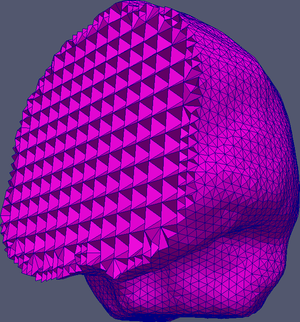
| − | |[[File:brain_after_section.jpg|thumb|300px|Brain BCC mesh | + | |[[File:brain_after_section.jpg|thumb|300px|Brain BCC mesh (cross-section) after MC]] |
|} | |} | ||
| Line 39: | Line 39: | ||
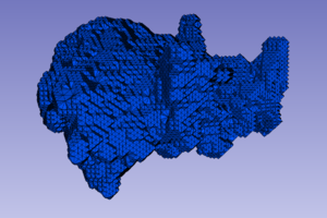
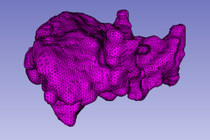
|[[File:nidus_before.jpg|thumb|300px|Nidus BCC mesh before MC]] | |[[File:nidus_before.jpg|thumb|300px|Nidus BCC mesh before MC]] | ||
|[[File:nidus_after.jpg|thumb|300px|Nidus BCC mesh after MC]]<br> | |[[File:nidus_after.jpg|thumb|300px|Nidus BCC mesh after MC]]<br> | ||
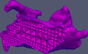
| − | |[[File:nidus_after_section.jpg|thumb|300px|Nidus BCC mesh | + | |[[File:nidus_after_section.jpg|thumb|300px|Nidus BCC mesh (cross-section) after MC]] |
|} | |} | ||
| Line 45: | Line 45: | ||
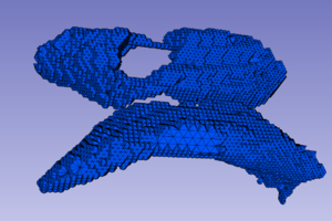
|[[File:ventricles_before.jpg|thumb|300px|Ventricles BCC mesh before MC]] | |[[File:ventricles_before.jpg|thumb|300px|Ventricles BCC mesh before MC]] | ||
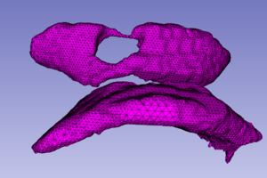
|[[File:ventricles_after.jpg|thumb|300px|Ventricles BCC mesh after MC]] | |[[File:ventricles_after.jpg|thumb|300px|Ventricles BCC mesh after MC]] | ||
| − | |[[File:ventricles_after_section.jpg|thumb|300px|Ventricles BCC mesh | + | |[[File:ventricles_after_section.jpg|thumb|300px|Ventricles BCC mesh (cross-section) after MC]] |
|} | |} | ||
Revision as of 14:13, 20 June 2014
Home < Documentation < Nightly < Modules < MeshCompression
|
For the latest Slicer documentation, visit the read-the-docs. |
Introduction and Acknowledgements
|
Extension: Image-To-Mesh (I2M) Conversion
Author: Fotis Drakopoulos | |||
|
Module Description
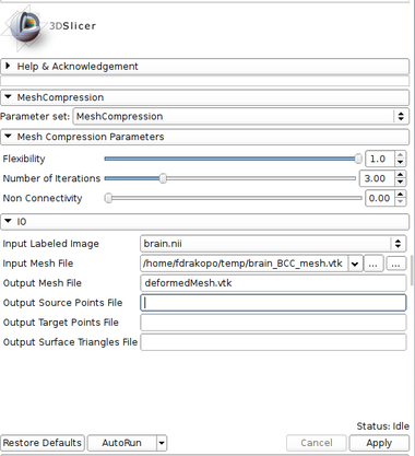
The Mesh Compression (MC) module deforms the input tetrahedral mesh towards the boundaries of the input labeled image. Two point sets are extracted for the mesh deformation. The first (source point set) consists of the surface vertices in the input mesh. The second (target point set) consists of the surface edge points in the input labeled image. After the extraction of the two point sets, the input mesh is deformed by registering the source to the target point set using a Physics-Based Non-Rigid Registration method. The current version of the module supports a single-tissue labeled image and mesh.
Use Cases
Tutorials
N/A
Panels and their use
|
Similar Modules
References
- Yixun Liu, Panagiotis Foteinos, Andrey Chernikov and Nikos Chrisochoides, "Mesh Deformation-based Multi-tissue Mesh Generation for Brain Images", Engineering with Computers, Volume 28, pages 305-318, 2012.
Information for Developers
| Section under construction. |

