Difference between revisions of "Modules:StochasticTractography-Documentation-3.4"
| (38 intermediate revisions by 2 users not shown) | |||
| Line 1: | Line 1: | ||
| − | + | [[Documentation-3.4|Return to Slicer 3.4 Documentation]] | |
| + | |||
| + | [[Announcements:Slicer3.4#Highlights|Gallery of New Features]] | ||
__NOTOC__ | __NOTOC__ | ||
===Module Name=== | ===Module Name=== | ||
| Line 19: | Line 21: | ||
* Author: Julien von Siebenthal | * Author: Julien von Siebenthal | ||
* Contributor: Steve Pieper | * Contributor: Steve Pieper | ||
| − | * Contact: | + | * Contact: Ryan Eckbo, PNL, reckbo at bwh.harvard.edu |
===Module Description=== | ===Module Description=== | ||
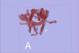
| − | As a main purpose, the stochastic tractography module helps to evaluate connectivity between two regions of | + | As a main purpose, the stochastic tractography module helps to evaluate connectivity between two regions of interest (ROIs) of the brain. These ROIs define generally grey matter regions having a specific neurophysiological function. Extensively, study involving more than two regions could still be done by pairing the regions two by two. |
| + | |||
| + | To go deeper into learning the module you can download the following [http://www.na-mic.org/Wiki/index.php/Python_Stochastic_Tractography_Tutorial tutorial] | ||
== Usage == | == Usage == | ||
| − | * want to study fiber path from a single | + | * You want to study fiber path from a single region of interest (ROI) |
| − | * want to evaluate connectivity between two | + | * You want to evaluate connectivity between two ROIs |
| − | |||
=== Description === | === Description === | ||
| − | |||
{| | {| | ||
| Line 36: | Line 38: | ||
|} | |} | ||
| − | * | + | With the stochastic tractography module, you can: |
| + | {| | ||
| + | | | ||
| + | * Feature 1 : smooth the given Diffusion Weighted Image (DWI) using a Half Width Full Maximum gaussian filter | ||
| + | {| | ||
| + | |[[Image:smooth2.png|thumb|500px|Smoothing step]] | ||
| + | |} | ||
| + | |} | ||
{| | {| | ||
| − | | | + | | |
| + | * Feature 2 : generate a brain mask from the DWI baseline input | ||
| + | {| | ||
|[[Image:mask2.png|thumb|500px|Brain mask step]] | |[[Image:mask2.png|thumb|500px|Brain mask step]] | ||
| + | |} | ||
|} | |} | ||
| − | * | + | {| |
| − | + | | | |
| + | * Feature 3 : create a DTI (Diffusion Tensor Image) tensor from the DWI input | ||
{| | {| | ||
|[[Image:tensor2.png|thumb|500px|Tensor step]] | |[[Image:tensor2.png|thumb|500px|Tensor step]] | ||
| − | | | + | |} |
|} | |} | ||
| − | |||
| − | |||
{| | {| | ||
| + | | | ||
| + | * Feature 4 : produce different measures based on the tensor like fractional anistropy (FA), mode and trace | ||
| + | {| | ||
| + | |[[Image:fa2.png|thumb|500px|Tensor step: FA]] | ||
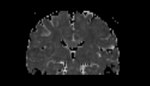
|[[Image:mode2.png|thumb|500px|Tensor step: mode]] | |[[Image:mode2.png|thumb|500px|Tensor step: mode]] | ||
|[[Image:trace2.png|thumb|500px|Tensor step: trace]] | |[[Image:trace2.png|thumb|500px|Tensor step: trace]] | ||
| + | |} | ||
|} | |} | ||
| − | * | + | {| |
| − | + | | | |
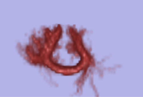
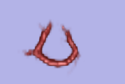
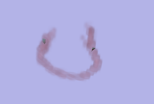
| + | * Feature 5 : produce connection maps in case 2 ROIs are given without ROI filtering from the tractography | ||
| + | ** showing union and intersection of both maps from region A to region B and B to A | ||
{| | {| | ||
|[[Image:AorB2.png|thumb|500px|Union of A to B and B to A]] | |[[Image:AorB2.png|thumb|500px|Union of A to B and B to A]] | ||
|[[Image:AandB2.png|thumb|500px|Intersection of A to B and B to A]] | |[[Image:AandB2.png|thumb|500px|Intersection of A to B and B to A]] | ||
| + | |} | ||
|} | |} | ||
| + | {| | ||
| + | | | ||
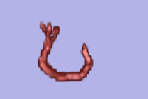
| + | * Feature 6 : produce connection maps in case 2 ROIs are given with ROI filtering from the tractography | ||
| + | ** showing only tracts connecting region A to region B and B to A | ||
{| | {| | ||
|[[Image:connectAB2.png|thumb|500px|ROI filtering]] | |[[Image:connectAB2.png|thumb|500px|ROI filtering]] | ||
|[[Image:A2B2.png|thumb|500px|ROI filtering from A to B]] | |[[Image:A2B2.png|thumb|500px|ROI filtering from A to B]] | ||
|[[Image:B2A2.png|thumb|500px|ROI filtering from B to A]] | |[[Image:B2A2.png|thumb|500px|ROI filtering from B to A]] | ||
| + | |} | ||
|} | |} | ||
| − | |||
===Quick Tour of Features and Use=== | ===Quick Tour of Features and Use=== | ||
| − | |||
| + | {| | ||
| + | | | ||
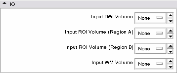
* '''IO panel:''' | * '''IO panel:''' | ||
| − | [[Image:IOmenu.png]] | + | ** Input DWI Volume: the DWI is loaded through the Volume module - it is th only mandatory input |
| + | ** Input ROI Volume (A/B): only 1 ROI is needed to achieve a tractography. If you want to evaluate the connection between two regions, you will give both ROIs | ||
| + | ** Input WM Volume: a white matter mask can be given as input to use ones provided by other tools or Slicer modules - it will supersede the brain mask even if enabled. Be mindful in setting a WM: tractography results can be impaired by a too restrictive WM | ||
| + | ** You are not obliged to set the ROIs or the white matter mask to smooth the DWI, create the brain mask and the tensor. These 3 features just require a DWI | ||
| + | {| | ||
| + | |[[Image:IOmenu.png|thumb|500px|IO step]] | ||
| + | |} | ||
| + | |} | ||
| + | |||
| + | {| | ||
| + | | | ||
* '''Smoothing panel:''' | * '''Smoothing panel:''' | ||
| − | [[Image:Smoothmenu.png]] | + | ** Gaussian FWHM: this filter defines a Full Width Half Maximum. You can define it for each direction in modifying each component of the 3-vector |
| + | ** Advice: you can enable solely that functionality and compute several times with different parameters till satisfaction | ||
| + | {| | ||
| + | |[[Image:Smoothmenu.png|thumb|500px|Smoothing step]] | ||
| + | |} | ||
| + | |} | ||
| + | |||
| + | {| | ||
| + | | | ||
* '''Brain Mask panel:''' | * '''Brain Mask panel:''' | ||
| − | [[Image:Maskmenu.png]] | + | ** Lower/Higher Brain Threshold: this filter is based on a simple level set segmentation - intensities of the baseline lying between the two values will be represented, others are set to 0. The most common use of this filter is to remove ventricles from the tractography domain and most of the outside of the brain |
| + | ** Advice: you can enable solely that functionality and compute several times with different parameters till satisfaction | ||
| + | {| | ||
| + | |[[Image:Maskmenu.png|thumb|500px|Brain mask step]] | ||
| + | |} | ||
| + | |} | ||
| + | |||
| + | {| | ||
| + | | | ||
* '''Diffusion Tensor panel:''' | * '''Diffusion Tensor panel:''' | ||
| − | [[Image:Tensormenu.png]] | + | ** Important: this step is not mandatory. It is here to evaluate the whole tensor and achieve measurements like FA, mode or trace. You did not need it to achieve tractography |
| − | * '''Tractography panel:''' | + | ** FA, mode and trace are sent as scalar volumes and inserted in the MRML tree to be further used |
| − | [[Image:Tractomenu.png]] | + | ** Advice: you can enable solely that functionality and compute several times with different parameters till satisfaction |
| − | * '''Connectivity Map panel:''' | + | {| |
| − | [[Image:Connectmenu.png]] | + | |[[Image:Tensormenu.png|thumb|500px|Tensor step]] |
| + | |} | ||
| + | |} | ||
| + | |||
| + | {| | ||
| + | | | ||
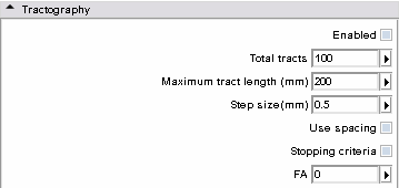
| + | * '''Tractography panel:''' This panel deals with the tractography per se: | ||
| + | ** Total tracts: number of generated tracts per voxel | ||
| + | ** Maximum tract length (mm): set the maximum length a tract could reach | ||
| + | ** Step size (mm): is the step length for the update vector | ||
| + | ** Use spacing: must be used with caution - activate spacing of the update vector | ||
| + | ** Stopping criteria: FA is used as the stopping criteria. Advice: as ROIs are defined in the grey matter FA are generally very low, therefore do not use it in most cases | ||
| + | {| | ||
| + | |[[Image:Tractomenu.png|thumb|500px|Tractography step]] | ||
| + | |} | ||
| + | |} | ||
| + | |||
| + | {| | ||
| + | | | ||
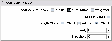
| + | * '''Connectivity Map panel:''' This panel lets the user modify parameters to create density/connectivity maps. A map is a scalar volume storing the number of times each voxel is traversed by tracts. It can be counted differently which is the purpose of the following parameters: | ||
| + | ** Computation mode: | ||
| + | *** binary: voxel counter is incremented by 1 only once | ||
| + | *** cumulative: voxel counter is incremented by 1 each time a tract traverses it | ||
| + | *** weighted: same as cumulative but the increment is the length of the tract traversing the voxel | ||
| + | ** Length based: must be enabled if the resulting tracts must be subdivided related to their length ownership | ||
| + | *** dThird: tracts only counted have length between 1 and (maximum tract length)/3 | ||
| + | *** mThird: tracts only counted have length between (maximum tract length)/3 and 2 * (maximum tract length)/3 | ||
| + | *** uThird: tracts only counted have length between 2 * (maximum tract length)/3 and (maximum tract length) | ||
| + | *** vicinity: in case of 2 ROIs connectivity assessment, setting vicinity to a positive value creates a neighborhood (in voxels) around the ROIs. This could help in counting tracts that ternminate near the ROIs but not accurately in | ||
| + | *** threshold: defines the connection probability under which tracts are rejected | ||
| + | {| | ||
| + | |[[Image:Connectmenu.png|thumb|500px|Connectivity step]] | ||
| + | |} | ||
| + | |} | ||
| + | |||
== Development == | == Development == | ||
| Line 96: | Line 180: | ||
Follow this [http://na-mic.org/Mantis/main_page.php link] to the Slicer3 bug tracker. | Follow this [http://na-mic.org/Mantis/main_page.php link] to the Slicer3 bug tracker. | ||
| − | |||
Latest revision as of 21:14, 30 March 2010
Home < Modules:StochasticTractography-Documentation-3.4Return to Slicer 3.4 Documentation
Module Name
Stochastic Tractography
General Information
Module Type & Category
Type: Interactive
Category: DTI
Authors, Collaborators & Contact
- Author: Julien von Siebenthal
- Contributor: Steve Pieper
- Contact: Ryan Eckbo, PNL, reckbo at bwh.harvard.edu
Module Description
As a main purpose, the stochastic tractography module helps to evaluate connectivity between two regions of interest (ROIs) of the brain. These ROIs define generally grey matter regions having a specific neurophysiological function. Extensively, study involving more than two regions could still be done by pairing the regions two by two.
To go deeper into learning the module you can download the following tutorial
Usage
- You want to study fiber path from a single region of interest (ROI)
- You want to evaluate connectivity between two ROIs
Description
With the stochastic tractography module, you can:
|
|
|
|
|
|
Quick Tour of Features and Use
|
|
|
|
|
|
Development
Dependencies
Volumes
Known bugs
Follow this link to the Slicer3 bug tracker.
Usability issues
Follow this link to the Slicer3 bug tracker. Please select the usability issue category when browsing or contributing.
Source code & documentation
More Information
Acknowledgment
National Alliance for Medical Image Computing (NAMIC), funded by the National Institutes of Health through the NIH Roadmap for Medical Research, Grant U54 EB005149 (to Ron Kikinis, Marek Kubicki).
References
- Björnemo M, Brun A, Kikinis R, Westin CF. Regularized stochastic white matter tractography using diffusion tensor MRI. In Fifth International Conference on Medical Image Computing and Computer-Assisted Intervention (MICCAI'02). Tokyo, Japan, 2002;435-442.
- Friman, O., Farneback, G., Westin CF. A Bayesian Approach for Stochastic White Matter Tractography. IEEE Transactions on Medical Imaging, Vol 25, No. 8, Aug. 2006
- Shenton, M.E., Ngo, T., Rosenberger, G., Westin, C.F., Levitt, J.J., McCarley, R.W., Kubicki, M. Study of Thalamo-Cortical White Matter Fiber Tract Projections in Schizophrenia Using Diffusion Stochastic Tractography. Poster presented at the 46th Meeting of the American College of Neuropsychopharmacology, Boca Raton, FL, December 2007.

