Difference between revisions of "Documentation/Nightly/Extensions/ScatteredTransform"
Grandwork2 (talk | contribs) |
Grandwork2 (talk | contribs) |
||
| (7 intermediate revisions by the same user not shown) | |||
| Line 28: | Line 28: | ||
2. Create a B-Spline transform based on two sets of points read from files. | 2. Create a B-Spline transform based on two sets of points read from files. | ||
These files can contain the initial and deform configurations for a biomechanics-based FEM or mesh-free registration. | These files can contain the initial and deform configurations for a biomechanics-based FEM or mesh-free registration. | ||
| − | The resulting B-Spline transform can be used to warp 3D images, a process which is very time consuming if spatial interpolation is performed using the mesh [1]. | + | The resulting B-Spline transform can be used to warp 3D images, a process which is very time consuming if spatial interpolation is performed using the mesh [1]. This module reduces the image warping time from hours to seconds. |
{| | {| | ||
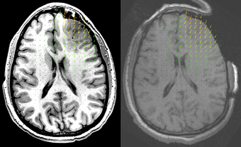
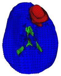
|[[Image:ScatteredTransform_displacementField.png|thumb|340px|Brain shift computed using a biomechanics based brain model and FEM. The deformed high resolution pre-operative image (left) is compared to the intra-operative image (right). The pre-operative image has been warped using the B-Spline obtained by applying ScatteredTransform to the original and deformed mesh nodal positions.]] | |[[Image:ScatteredTransform_displacementField.png|thumb|340px|Brain shift computed using a biomechanics based brain model and FEM. The deformed high resolution pre-operative image (left) is compared to the intra-operative image (right). The pre-operative image has been warped using the B-Spline obtained by applying ScatteredTransform to the original and deformed mesh nodal positions.]] | ||
| Line 39: | Line 39: | ||
{| | {| | ||
| | | | ||
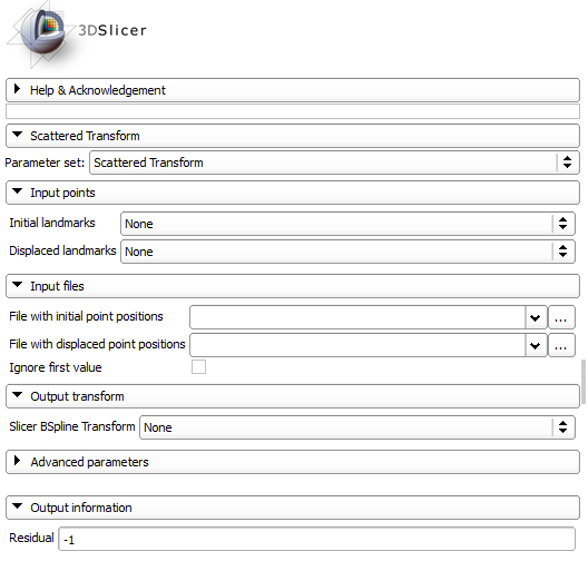
| − | |[[ScatteredTransform_panel.png|thumb| | + | |[[Image:ScatteredTransform_panel.png|thumb|560px|Module UI]] |
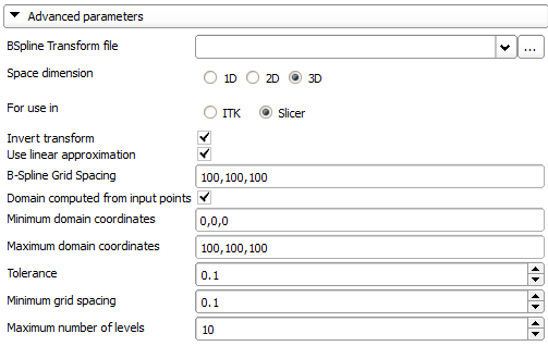
| + | |[[Image:ScatteredTransform_panelAdvanced.png|thumb|560px|Advanced parameters]] | ||
|} | |} | ||
| − | + | <UL> | |
| + | <strong>Input points:</strong> | ||
| + | <LI>Initial landmarks: Ordered list of fiducials in initial position. Select these from the moving image if the resulting transform is used for image registration.</LI> | ||
| + | <LI>Displaced landmarks: Ordered list of fiducials in displaced position. Select these from the fixed image if the resulting transform is used for image registration.</LI> | ||
| + | <strong>Input files:</strong> | ||
| + | <LI>File with initial point positions: File with coordinates of points in initial position.</LI> | ||
| + | <LI>File with displaced point positions: File with coordinates of points in displaced position.</LI> | ||
| + | <LI>Ignore first value: Ignores first value in each line of the input files (which may be a node number).</LI> | ||
| + | <strong>Output transform:</strong> | ||
| + | <LI>Slicer BSpline Transform: Slicer transform node for the generated B-Spline transform. NOTE: Only 3D transforms are handled by 3D Slicer!</LI> | ||
| + | <strong>Advanced parameters:</strong> | ||
| + | <LI>BSpline Transform file: File where to save the transform. Needed for 1D and 2D transforms, as Slicer does not create a transform node for these transforms.</LI> | ||
| + | <LI>Space dimension: The space dimension (1D, 2D or 3D).</LI> | ||
| + | <LI>For use in: Where is the transform going to be used? If the transform is a 3D transform to be used in Slicer, a coordinate transformation (similar to what Slicer does internally) is applied to the coordinates before the transform is computed.(only 3D transforms can be used in Slicer)</LI> | ||
| + | <LI>Invert transform: Inverts the transform. Always done if transform is for use in Slicer.</LI> | ||
| + | <LI>Use linear approximation: Sets the initial B-Spline grid values using a linear approximation of the displacements.</LI> | ||
| + | <LI>B-Spline Grid Spacing: The distance between the BSpline control grid points.</LI> | ||
| + | <LI>Domain computed from input points: Computes the transform domain as the bounding box of the input points.</LI> | ||
| + | <LI>Minimum domain coordinates: The minimum coordinates of the domain (if not computed from input points).</LI> | ||
| + | <LI>Maximum domain coordinates: The maximum coordinates of the domain (if not computed from input points).</LI> | ||
| + | <LI>Tolerance: Absolute tolerance in approximating the transform at the input points.</LI> | ||
| + | <LI>Minimum grid spacing: Minimum grid spacing during grid refinement.</LI> | ||
| + | <LI>Maximum number of levels: Maximum number of levels of B-Spline refinements.</LI> | ||
| + | <strong>Output information:</strong> | ||
| + | <LI>Residual: Display residual approximation error on successful completion.</LI> | ||
| + | </UL> | ||
<!-- ---------------------------- --> | <!-- ---------------------------- --> | ||
{{documentation/{{documentation/version}}/module-section|References}} | {{documentation/{{documentation/version}}/module-section|References}} | ||
| Line 50: | Line 76: | ||
<!-- ---------------------------- --> | <!-- ---------------------------- --> | ||
{{documentation/{{documentation/version}}/module-footer}} | {{documentation/{{documentation/version}}/module-footer}} | ||
| − | [[Category:Documentation/{{documentation/version}}/ | + | [[Category:Documentation/{{documentation/version}}/Extensions]] |
<!-- ---------------------------- --> | <!-- ---------------------------- --> | ||
Latest revision as of 06:19, 3 March 2017
Home < Documentation < Nightly < Extensions < ScatteredTransform
|
For the latest Slicer documentation, visit the read-the-docs. |
Introduction and Acknowledgements
|
Extension: ScatteredTransform |
Module Description
Creates a BSpline transform from a displacement field defined at scattered points by using the Multi-level BSpline interpolation algorithm.
Use Cases
1. Create a B-Spline transform based on two sets of fiducials.
2. Create a B-Spline transform based on two sets of points read from files. These files can contain the initial and deform configurations for a biomechanics-based FEM or mesh-free registration. The resulting B-Spline transform can be used to warp 3D images, a process which is very time consuming if spatial interpolation is performed using the mesh [1]. This module reduces the image warping time from hours to seconds.
Panels and their use
-
Input points:
- Initial landmarks: Ordered list of fiducials in initial position. Select these from the moving image if the resulting transform is used for image registration.
- Displaced landmarks: Ordered list of fiducials in displaced position. Select these from the fixed image if the resulting transform is used for image registration. Input files:
- File with initial point positions: File with coordinates of points in initial position.
- File with displaced point positions: File with coordinates of points in displaced position.
- Ignore first value: Ignores first value in each line of the input files (which may be a node number). Output transform:
- Slicer BSpline Transform: Slicer transform node for the generated B-Spline transform. NOTE: Only 3D transforms are handled by 3D Slicer! Advanced parameters:
- BSpline Transform file: File where to save the transform. Needed for 1D and 2D transforms, as Slicer does not create a transform node for these transforms.
- Space dimension: The space dimension (1D, 2D or 3D).
- For use in: Where is the transform going to be used? If the transform is a 3D transform to be used in Slicer, a coordinate transformation (similar to what Slicer does internally) is applied to the coordinates before the transform is computed.(only 3D transforms can be used in Slicer)
- Invert transform: Inverts the transform. Always done if transform is for use in Slicer.
- Use linear approximation: Sets the initial B-Spline grid values using a linear approximation of the displacements.
- B-Spline Grid Spacing: The distance between the BSpline control grid points.
- Domain computed from input points: Computes the transform domain as the bounding box of the input points.
- Minimum domain coordinates: The minimum coordinates of the domain (if not computed from input points).
- Maximum domain coordinates: The maximum coordinates of the domain (if not computed from input points).
- Tolerance: Absolute tolerance in approximating the transform at the input points.
- Minimum grid spacing: Minimum grid spacing during grid refinement.
- Maximum number of levels: Maximum number of levels of B-Spline refinements. Output information:
- Residual: Display residual approximation error on successful completion.
References
1. Joldes GR, Wittek A, Warfield SK, Miller K (2012) "Performing Brain Image Warping Using the Deformation Field Predicted by a Biomechanical Model." In: Nielsen PMF, Miller K, Wittek A, editors. Computational Biomechanics for Medicine: Deformation and Flow: Springer New York. pp. 89-96.


