Difference between revisions of "Documentation/Nightly/Modules/KSliceInteractiveSegmenter"
(Prepend documentation/versioncheck template. See http://na-mic.org/Mantis/view.php?id=2887) |
|||
| (8 intermediate revisions by the same user not shown) | |||
| Line 72: | Line 72: | ||
Step 1.) Add data volume to segment | Step 1.) Add data volume to segment | ||
| − | [[File: | + | [[File:LoadMeningioma.png|500px]] |
Step 2.) Go to the “Editor” module, select the volume loaded in Step 1 as the “Master Volume” in the “Create and Select Label Maps” drop-down menu | Step 2.) Go to the “Editor” module, select the volume loaded in Step 1 as the “Master Volume” in the “Create and Select Label Maps” drop-down menu | ||
| − | [[File: | + | [[File:StartEditorMeningioma.png|500px]] |
| Line 85: | Line 85: | ||
| − | Step 4.) Set the “Radius” parameter and press the “Start Interactive Segmentor” button ( KSlice is now running in the background until the “Stop Interactive Segmentor” button is pressed) | + | Step 4.) Set the “Radius” parameter, the "Number of Iterations" and press the “Start Interactive Segmentor” button ( KSlice is now running in the background until the “Stop Interactive Segmentor” button is pressed) |
| − | [[File: | + | [[File:StartBotMeningioma.png|500px]] |
Step 5.) Turn “On” all three slice views in the 3D Plane | Step 5.) Turn “On” all three slice views in the 3D Plane | ||
| − | [[File: | + | [[File:TurnOnSlices3DMeningioma.png|500px]] |
| − | Step 5.) Select the | + | Step 5.) Select the rectangle tool(or any other painting tool). |
| − | ( | ||
| − | [[File: | + | [[File:ImplicitRectangle.png|50px]] |
| − | and initialize KSlice by drawing inside the structure of interest | + | and initialize KSlice in a 2D slice by drawing inside the structure of interest. |
| − | [[File: | + | [[File:KSliceInitMeningioma.png|500px]] |
| − | |||
| − | + | Step 6.) Press the “C” key to copy the current initialization in this 2D plane, then press the left/right arrow on the keyboard to move on to an adjacent slice, press the “V” key to paste the label, thereby initializing the current slice. Once this procedure has been repeated several times, we have initialized the surface to a cube in 3D. | |
| + | [[File:KSliceInit3DCube.png|500px]] | ||
| − | |||
| − | + | Step 7.) To evolve the 2D contour on a slice, hover the mouse over a 2D view plane, press “Q”. | |
| + | [[File:KSlice2DEvolve.png|500px]] | ||
| − | |||
| − | |||
| − | + | Step 8.) Evolve the contour in 3D by pressing "E" to use the Chan-Vese energy. | |
| − | Step | ||
| − | |||
| − | |||
| Line 127: | Line 121: | ||
== As necessary, take steps at any time in the process == | == As necessary, take steps at any time in the process == | ||
| − | Step | + | Step 9.)(Used in any order) A segmenting surface may leak into undesirable areas, based purely on image data. It is the user's job to guide the evolution process. A user can provide positive input (drawing) by selecting a paint tool, painting in areas which should be part of the object of interest but are not. Or, the user can provide negative input (erasing) by pressing "A" (toggle label value between 0 and the originally selected label). An example of a user correction is going from |
| − | |||
| − | |||
| + | [[File:KSliceNegativeInput.png|500px]] | ||
| − | + | to | |
| − | [[File: | + | [[File:KSliceCorrectedUI.png|500px]] |
| + | Step 10.) (Used in any order) Certain image regions (depending on the energy chosen and the image itself) may be highly attractive for the evolving contour despite being incorrect according to the user's expert knowledge. He has two options. First, apply repeated input several times (soft user constraints). Second, he can press "B" (toggle between soft/hard constraints) to increase the weight on his inputs, essentially making them hard constraints. Further, constraints can be provided pre-emptively, by erasing/drawing in regions before a contour has reached these areas to prevent leaks in the future or expedite the evolution process, respectively. | ||
| − | |||
| − | + | Step 11.)(Used in any order) Press "F" to run the contour in 3D, similarly to Step.8 but using an alternative energy, the Local Global Chan-Vese. The user can switch the energy he is using at any time. | |
| Line 147: | Line 140: | ||
== Optional Visualization == | == Optional Visualization == | ||
| − | Step | + | Step 12.) (Optional) Turn on “Volume Rendering” of the label image in 3D (notice the parameters set for faster interaction). This will be updated during the evolution |
| − | [[File: | + | [[File:VolumeRederingOnMeningioma.png|500px]] |
---- <!-- Horizontal rule --> | ---- <!-- Horizontal rule --> | ||
| − | Step 14.) | + | Step 13.) Examine the current segmentation by flipping through the 2D viewers, providing input as in Step.9 to guide the evolution. |
| + | |||
| + | [[File:ExampleUIDuringProcess.png|500px]] | ||
| + | |||
| + | |||
| + | |||
| + | Step 14.) Repeat steps 7-11 (or any subset of them) until convergence to the desired segmentation. | ||
| + | |||
| + | [[File:KSliceFinalSegMeningioma.png|500px]] | ||
| − | |||
| − | Step 15.) Once | + | Step 15.) Once satisfied with the segmentation, stop KSlice by clicking "Stop Interactive Segmentor" |
| − | [[File: | + | [[File:StopInteractiveSegmenter.png|500px]] |
| Line 167: | Line 167: | ||
<!-- ---------------------------- --> | <!-- ---------------------------- --> | ||
{{documentation/{{documentation/version}}/module-section|Panels and their use}} | {{documentation/{{documentation/version}}/module-section|Panels and their use}} | ||
| − | There | + | There are two parameters to set: the radius that sets the band around the current initialisation in which image data is considered (for Local-Global Chan-Vese energy) and the number of contour iterations. A large radius means data from far lying regions influences the segmentation (this increases the computational complexity). A small radius ensures that only nearby pixels influence the contour (but set too small will require a better contour initialisation from the user). The number of iterations refers to the time for which the segmenting surface is allowed to evolve before querying the user for input. A small number allows the user to catch the surface before a large error is made, reducing corrective inputs required but may be tedious/slow. |
Latest revision as of 19:44, 20 September 2013
Home < Documentation < Nightly < Modules < KSliceInteractiveSegmenter
|
For the latest Slicer documentation, visit the read-the-docs. |
Introduction and Acknowledgements
|
This work is part of the National Alliance for Medical Image Computing (NA-MIC), funded by the National Institutes of Health through the NIH Roadmap for Medical Research, Grant U54 EB005149. Information on NA-MIC can be obtained from the NA-MIC website. Author: Ivan Kolesov, Georgia Institute of Technology |
|
|
Module Description
This is the KSlice interactive segmentation method. It uses a data-driven automatic algorithm to process the majority of the volume. As the automatic segmentation runs and displays the current state, a human user can influence the algorithm’s behavior to more closely align with an expected result. In the end, the user has created an excellent segmentation result with a minimal amount of time and effort. Please see the references below for more details.
Tutorials
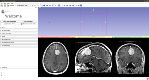
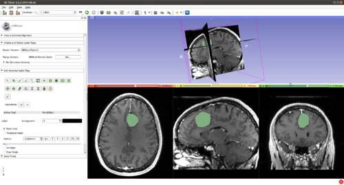
Step 1.) Add data volume to segment
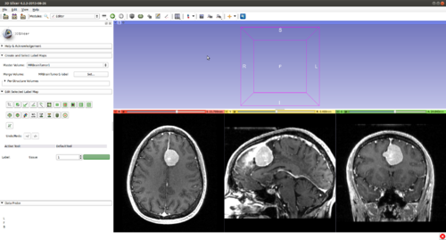
Step 2.) Go to the “Editor” module, select the volume loaded in Step 1 as the “Master Volume” in the “Create and Select Label Maps” drop-down menu
Step 3.) Select the “KSlice” effect in the “Edit Selected Label Map” drop-down menu
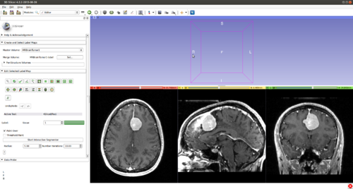
Step 4.) Set the “Radius” parameter, the "Number of Iterations" and press the “Start Interactive Segmentor” button ( KSlice is now running in the background until the “Stop Interactive Segmentor” button is pressed)
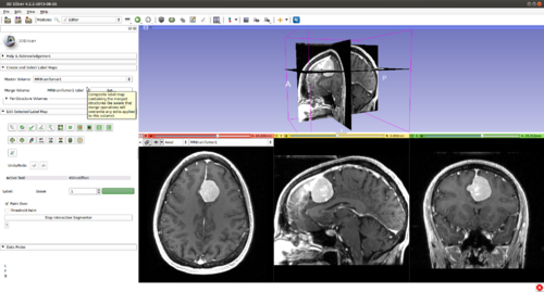
Step 5.) Turn “On” all three slice views in the 3D Plane
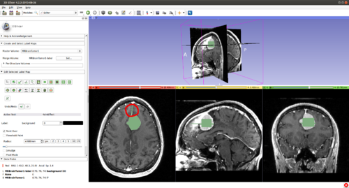
Step 5.) Select the rectangle tool(or any other painting tool).
and initialize KSlice in a 2D slice by drawing inside the structure of interest.
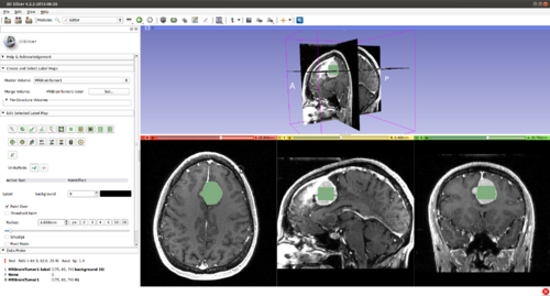
Step 6.) Press the “C” key to copy the current initialization in this 2D plane, then press the left/right arrow on the keyboard to move on to an adjacent slice, press the “V” key to paste the label, thereby initializing the current slice. Once this procedure has been repeated several times, we have initialized the surface to a cube in 3D.
Step 7.) To evolve the 2D contour on a slice, hover the mouse over a 2D view plane, press “Q”.
Step 8.) Evolve the contour in 3D by pressing "E" to use the Chan-Vese energy.
As necessary, take steps at any time in the process
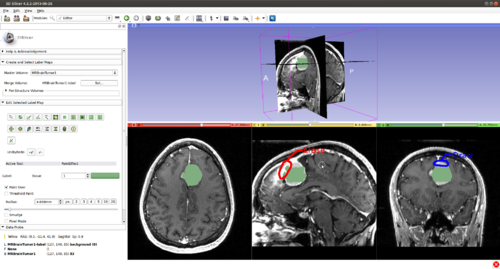
Step 9.)(Used in any order) A segmenting surface may leak into undesirable areas, based purely on image data. It is the user's job to guide the evolution process. A user can provide positive input (drawing) by selecting a paint tool, painting in areas which should be part of the object of interest but are not. Or, the user can provide negative input (erasing) by pressing "A" (toggle label value between 0 and the originally selected label). An example of a user correction is going from
to
Step 10.) (Used in any order) Certain image regions (depending on the energy chosen and the image itself) may be highly attractive for the evolving contour despite being incorrect according to the user's expert knowledge. He has two options. First, apply repeated input several times (soft user constraints). Second, he can press "B" (toggle between soft/hard constraints) to increase the weight on his inputs, essentially making them hard constraints. Further, constraints can be provided pre-emptively, by erasing/drawing in regions before a contour has reached these areas to prevent leaks in the future or expedite the evolution process, respectively.
Step 11.)(Used in any order) Press "F" to run the contour in 3D, similarly to Step.8 but using an alternative energy, the Local Global Chan-Vese. The user can switch the energy he is using at any time.
Optional Visualization
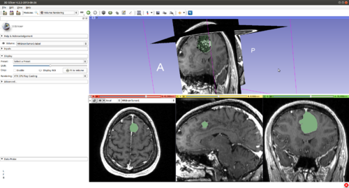
Step 12.) (Optional) Turn on “Volume Rendering” of the label image in 3D (notice the parameters set for faster interaction). This will be updated during the evolution
Step 13.) Examine the current segmentation by flipping through the 2D viewers, providing input as in Step.9 to guide the evolution.
Step 14.) Repeat steps 7-11 (or any subset of them) until convergence to the desired segmentation.
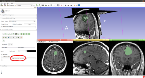
Step 15.) Once satisfied with the segmentation, stop KSlice by clicking "Stop Interactive Segmentor"
Panels and their use
There are two parameters to set: the radius that sets the band around the current initialisation in which image data is considered (for Local-Global Chan-Vese energy) and the number of contour iterations. A large radius means data from far lying regions influences the segmentation (this increases the computational complexity). A small radius ensures that only nearby pixels influence the contour (but set too small will require a better contour initialisation from the user). The number of iterations refers to the time for which the segmenting surface is allowed to evolve before querying the user for input. A small number allows the user to catch the surface before a large error is made, reducing corrective inputs required but may be tedious/slow.
References
- Kolesov, I., Karasev, P., Muller, G., Chudy, K., Xerogeanes, J., and Tannenbaum, A., “Human supervisory control framework for interactive medical image segmentation,” in International Conference on Medical Image Computing and Computer Assisted Intervention (MICCAI) Computational Biomechanics for Medicine Workshop, Proceeding of the, 2011.
- Karasev, P., Kolesov, I., Chudy, K., Muller, G., Xerogeanes, J., and Tannenbaum, A., “Interactive mri segmentation with controlled active vision,” in IEEE Conference on Decision and Control, Proceedings of the, IEEE, Dec. 2011.
- Karasev, P., Kolesov, I., Fritscher, K., Vela, P., Mitchell, P., and Tannenbaum, A.. “Interactive Medical Image Segmentation using PDE Control Of Active Contours”. In: Medical Imaging, IEEE Transactions on (In Submission) (2013)
- Xerogeanes, J., Mitchell, P. , Karasev, P., Kolesov, I. and Romine, S. . “An Anatomic and Morphologic Evaluation of the Quadriceps Tendon Using 3D MRI Reconstruction: Applications for ACL Autograft Choice and Procurement”. In: Journal of Bone and Joint Surgery (In Submission) (2013)
Information for Developers
| Section under construction. |
