Difference between revisions of "Modules:N4ITKBiasFieldCorrection-Documentation-3.6"
| (7 intermediate revisions by the same user not shown) | |||
| Line 18: | Line 18: | ||
Type: CLI | Type: CLI | ||
| − | Category: Filtering | + | Category: Filtering |
===Authors, Collaborators & Contact=== | ===Authors, Collaborators & Contact=== | ||
| Line 26: | Line 26: | ||
===Module Description=== | ===Module Description=== | ||
| − | This module is a CLI wrapper around the N4 bias field correction algorithm, which was presented by Nick Tustison in [http://hdl.handle.net/10380/3053 this Insight Journal publication]. This module can be used to remove field inhomogeneity artifact from the image. | + | This module is a CLI wrapper around the N4 bias field correction algorithm, which was presented by Nick Tustison in [http://hdl.handle.net/10380/3053 this Insight Journal publication]. This module can be used to remove field inhomogeneity artifact from the image. The module is based on the version 9 of the Insight Journal contribution, with minor changes to the processing filters to track execution progress and to fix some minor issues. |
== Usage == | == Usage == | ||
| Line 47: | Line 47: | ||
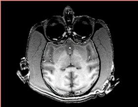
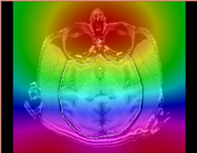
|[[Image:n4_mark1_input.png|thumb|280px|Slice of the input test volume with apparent bias field and label outlines]] | |[[Image:n4_mark1_input.png|thumb|280px|Slice of the input test volume with apparent bias field and label outlines]] | ||
|[[Image:n4_mark1_output.png|thumb|280px|Output image visually contains less inhomogeneity]] | |[[Image:n4_mark1_output.png|thumb|280px|Output image visually contains less inhomogeneity]] | ||
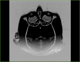
| + | |[[Image:n4_mark1_subtract.png|thumb|280px|Before - After subtract image]] | ||
|[[Image:n4_mark1_bias.png|thumb|280px|Recovered bias field]] | |[[Image:n4_mark1_bias.png|thumb|280px|Recovered bias field]] | ||
|} | |} | ||
| Line 65: | Line 66: | ||
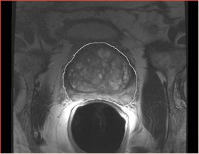
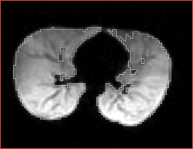
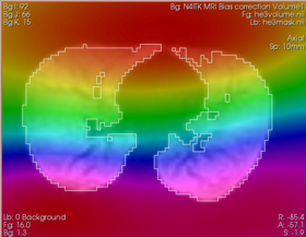
|[[Image:n4_he_input.png|thumb|280px|Slice of the input test volume with apparent bias field and label outlines]] | |[[Image:n4_he_input.png|thumb|280px|Slice of the input test volume with apparent bias field and label outlines]] | ||
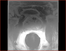
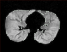
|[[Image:n4_he_output.png|thumb|280px|Output image visually contains less inhomogeneity]] | |[[Image:n4_he_output.png|thumb|280px|Output image visually contains less inhomogeneity]] | ||
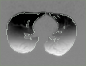
| + | |[[Image:n4_he_subtract.png|thumb|280px|Before - After subtract image]] | ||
|[[Image:n4_he_bias.png|thumb|280px|Recovered bias field (zoom in to see the actual value in the background image)]] | |[[Image:n4_he_bias.png|thumb|280px|Recovered bias field (zoom in to see the actual value in the background image)]] | ||
|} | |} | ||
| Line 95: | Line 97: | ||
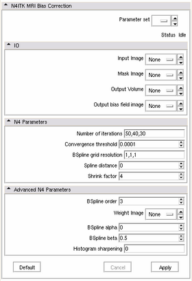
|[[Image:n4_controls.png|thumb|280px|User Interface]] | |[[Image:n4_controls.png|thumb|280px|User Interface]] | ||
|} | |} | ||
| + | |||
| + | * '''Bias correction in brain MRI''': It was shown that performance of bias correction for brain MRI is significantly improved when the bias estimation is limited to the brain region (see Boyes et al. in References). You might be able to achieve better results for your application if you provide a meaningful brain mask as a parameter to this module. | ||
== Development == | == Development == | ||
| Line 144: | Line 148: | ||
* Tustison N, Avants B, Cook P, Gee J ''N4ITK: Improved N3 Bias Correction with Robust B-Spline Approximation'', Proc. of ISBI'10, 2010 | * Tustison N, Avants B, Cook P, Gee J ''N4ITK: Improved N3 Bias Correction with Robust B-Spline Approximation'', Proc. of ISBI'10, 2010 | ||
* Tustison NJ, Avants BB, Cook PA, Zheng Y, Egan A, Yushkevich PA, Gee JC '' N4ITK: Improved N3 Bias Correction'', IEEE Trans Med Imag, 2010 [http://dx.doi.org/10.1109/TMI.2010.2046908 link] | * Tustison NJ, Avants BB, Cook PA, Zheng Y, Egan A, Yushkevich PA, Gee JC '' N4ITK: Improved N3 Bias Correction'', IEEE Trans Med Imag, 2010 [http://dx.doi.org/10.1109/TMI.2010.2046908 link] | ||
| + | * Boyes RG, Gunter JL, Frost C, Janke AL, Yeatman T, Hill DL, Bernstein MA, Thompson PM, Weiner MW, Schuff N, Alexander GE, Killiany RJ, DeCarli C, Jack CR, Fox NC (2008) ''Intensity non-uniformity correction using N3 on 3-T scanners with multichannel phased array coils''. NeuroImage 39:1752-62 [http://www.pubmedcentral.nih.gov/articlerender.fcgi?artid=2562663&tool=pmcentrez&rendertype=abstract link]. | ||
Latest revision as of 13:34, 20 October 2010
Home < Modules:N4ITKBiasFieldCorrection-Documentation-3.6Return to Slicer 3.6 Documentation
N4ITK Bias field correction
General Information
Module Type & Category
Type: CLI
Category: Filtering
Authors, Collaborators & Contact
- Author: Nick Tustison, UPenn (algorithm and ITK implementation)
- Author: Andriy Fedorov, BWH (Slicer integration)
- Contact: Andriy Fedorov, fedorov at bwh dot harvard dot edu
Module Description
This module is a CLI wrapper around the N4 bias field correction algorithm, which was presented by Nick Tustison in this Insight Journal publication. This module can be used to remove field inhomogeneity artifact from the image. The module is based on the version 9 of the Insight Journal contribution, with minor changes to the processing filters to track execution progress and to fix some minor issues.
Usage
With the basic usage scenario, you only need to specify the input and output images. You can improve the performance of this module by specifying the binary mask for the region of interest in your input image. If this mask is not specified, the module will use Otsu thresholding algorithm to estimate the mask automatically.
In case you are not happy with the result of processing, you may need to experiment with the parameters described below. If you are still not satisfied with the result, you will need to study the relevant papers (see References section at the bottom of this page) and/or contact the Slicer and ITK user lists.
Use Cases, Examples
This module is especially appropriate for these use cases:
- You observe smooth variation of the intensity over the tissue that should have intensity close to uniform
- Your attempts to segment or register your data are not successful, and you are not sure what to do next
Examples of the module in use:
- Correction of the bias in vervet MRI. Acquisition parameters: 3T GE scanner, single-channel dedicated RF coil (Litzcage, Doty Scientific, Columbia, SC); 3D SPGR sequence (TI 600ms, TE 3.276ms, TR 15.28ms; flip angle 15 deg; matrix 256x256; FOV 12cm; in-plane resolution 0.47 mm; slice thickness 0.5 mm).
- Example 2
Tutorials
There are no tutorials available at this time.
However, you can use the images that we use to test the functionality of this module, and the output it generates with the default values of the parameters to experiment with the parameters:
Quick Tour of Features and Use
The N4 algorithm uses a hierarchy of bspline grids to approximate the smooth inhomogeneity field present in the image.
|
- Bias correction in brain MRI: It was shown that performance of bias correction for brain MRI is significantly improved when the bias estimation is limited to the brain region (see Boyes et al. in References). You might be able to achieve better results for your application if you provide a meaningful brain mask as a parameter to this module.
Development
Notes from the Developer(s)
If you use this module in a Slicer installation compiled from source, it is very important that you compile in Release mode. The difference in performance can be as much as 10x between the Release mode and Debug mode (default mode used by Slicer build scripts). To ensure your installation uses Release mode, run the build script as follows:
Slicer3/Scripts/getbuildtest.tcl --release --clean
Dependencies
This is a shared library module that uses Slicer Execution Model, and therefore requires CommandLineModules to be enabled.
Tests
On the Dashboard, these tests verify that the module is working on various platforms:
Known bugs
No reported bugs.
Usability issues
Follow this link to the Slicer3 bug tracker. Please select the usability issue category when browsing or contributing.
Source code & documentation
Links to the module's source code:
Source code:
Doxygen documentation:
More Information
Acknowledgment
The development of this module was partially supported by NIH grants R01 AA016748-01 and R01 CA111288, as well as by NA-MIC, NAC, NCIGT and the Slicer community.
References
- Tustison N, Gee J N4ITK: Nick's N3 ITK Implementation For MRI Bias Field Correction, The Insight Journal 2009 January-June link
- Tustison N, Avants B, Cook P, Gee J N4ITK: Improved N3 Bias Correction with Robust B-Spline Approximation, Proc. of ISBI'10, 2010
- Tustison NJ, Avants BB, Cook PA, Zheng Y, Egan A, Yushkevich PA, Gee JC N4ITK: Improved N3 Bias Correction, IEEE Trans Med Imag, 2010 link
- Boyes RG, Gunter JL, Frost C, Janke AL, Yeatman T, Hill DL, Bernstein MA, Thompson PM, Weiner MW, Schuff N, Alexander GE, Killiany RJ, DeCarli C, Jack CR, Fox NC (2008) Intensity non-uniformity correction using N3 on 3-T scanners with multichannel phased array coils. NeuroImage 39:1752-62 link.
