Difference between revisions of "Documentation/4.4/gif tutorial"
From Slicer Wiki
| (10 intermediate revisions by the same user not shown) | |||
| Line 46: | Line 46: | ||
| − | === | + | ===Tractography exploration of peritumoral white matter fibers=== |
<div style="width: 62%; height:525px; overflow:auto; border: 2px solid #088; margin: 1em auto 1em auto;"> | <div style="width: 62%; height:525px; overflow:auto; border: 2px solid #088; margin: 1em auto 1em auto;"> | ||
{|style="width: 62%; height: 200px;" border="1" | {|style="width: 62%; height: 200px;" border="1" | ||
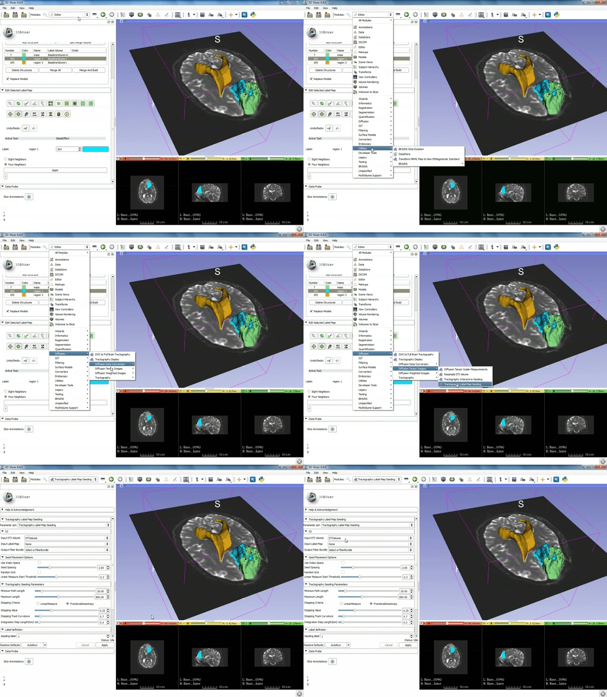
| − | |[[image:x.gif|600px|frame|1. | + | |[[image:x.gif|600px|frame|1. a) Make sure the cystic part is selected and visible in the 3 slice views. b) Click on the Dilate Effect tool then click on the cystic part of the tumor on the red slice view.]] |
|- style="height: 100px;" | |- style="height: 100px;" | ||
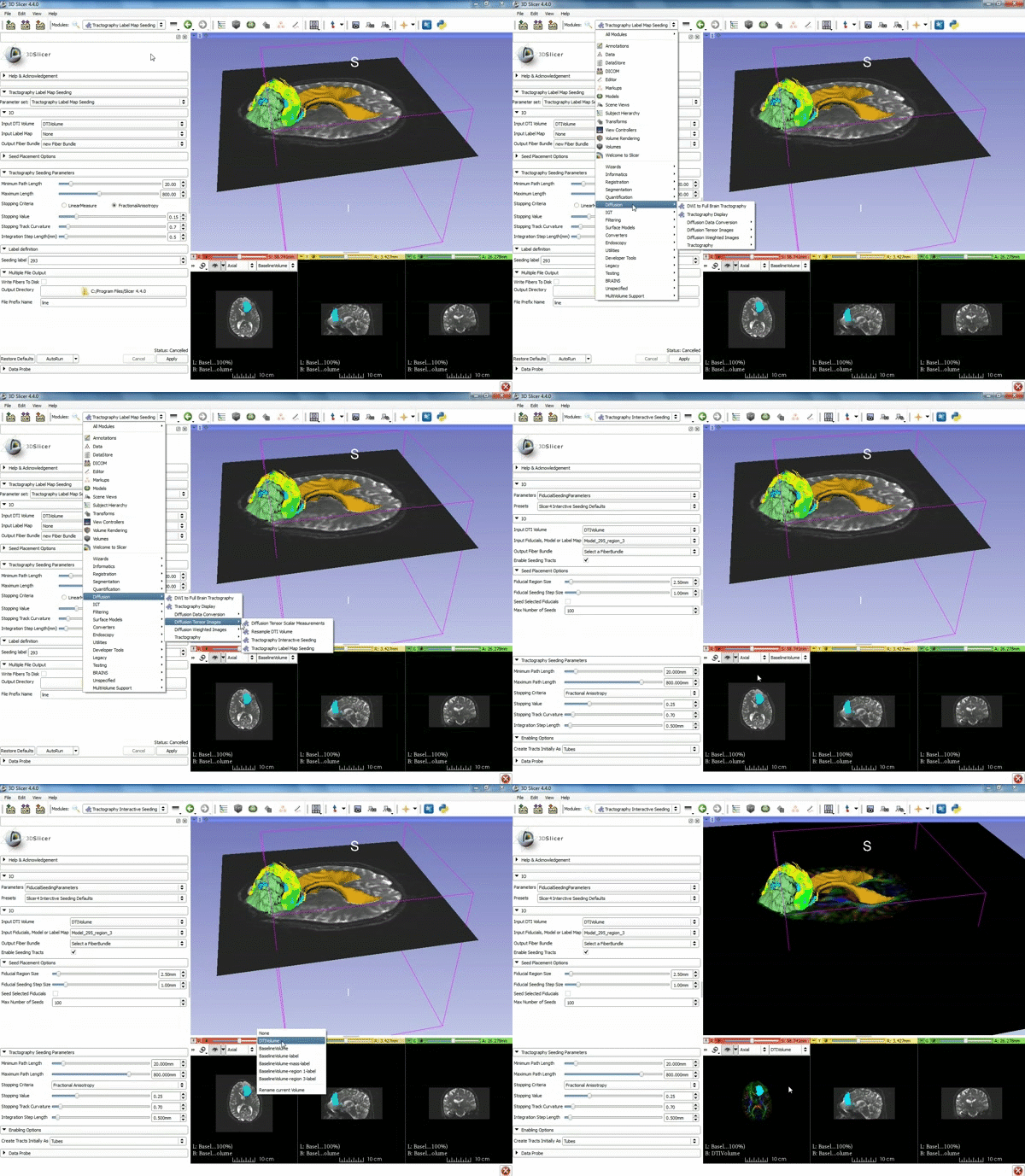
| − | |[[image:y.gif|600px|frame|2. Click on | + | |[[image:y.gif|600px|frame|2. Click on Apply 3 times to generate the peritumoral volume]] |
|- style="height: 100px;" | |- style="height: 100px;" | ||
| − | |[[image:z.gif|600px|frame|3. | + | |[[image:z.gif|600px|frame|3. Select the module "Tractography Label Map Seeding" by clicking "Editor" at the top, then "Diffusion", then "Diffusion Tensor Imaging".]] |
|- style="height: 100px;" | |- style="height: 100px;" | ||
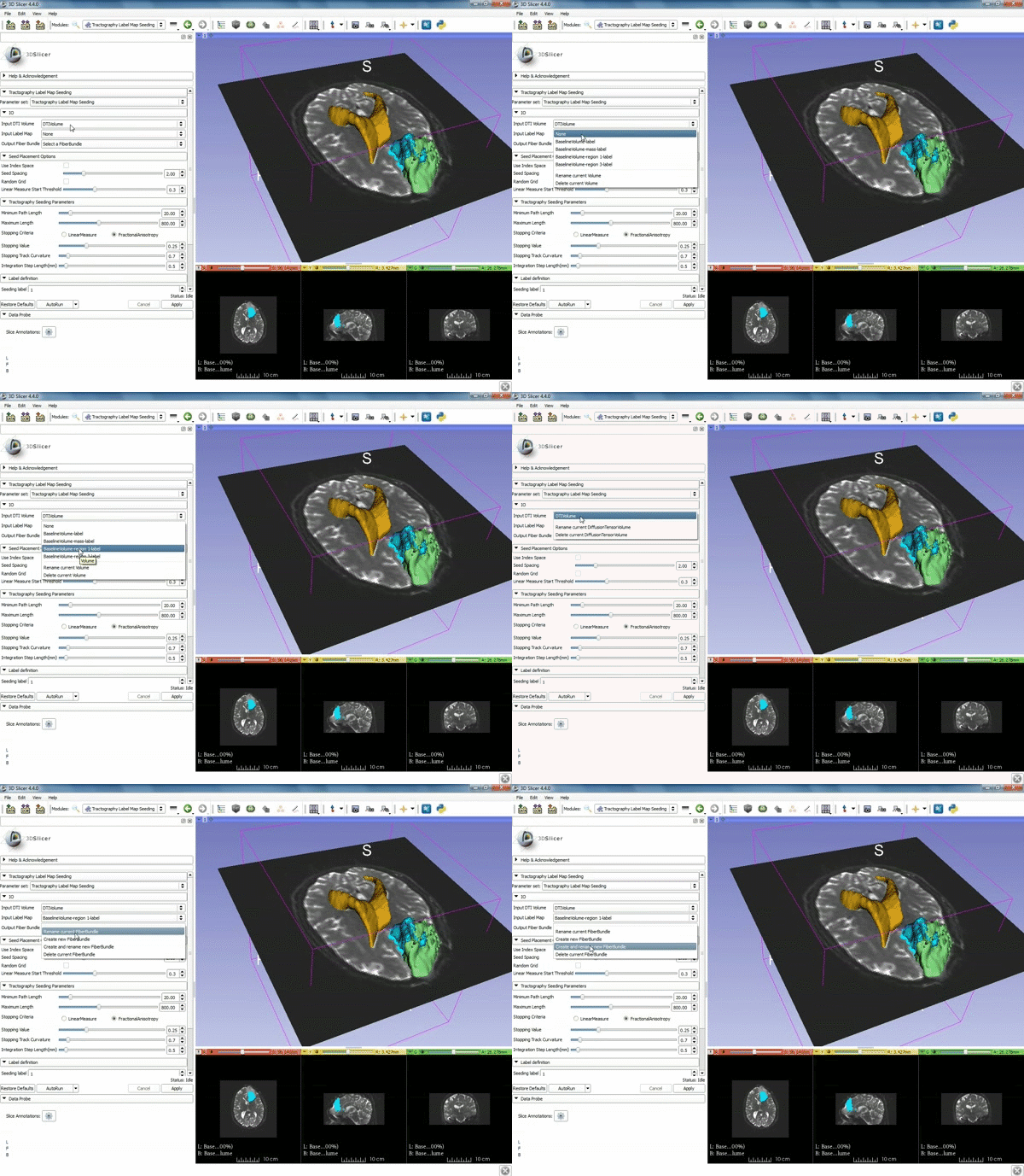
| − | |[[image:c.gif|600px|frame| | + | |[[image:c.gif|600px|frame|4. Make sure that "DTI Volume" is selected for Input DTI Volume and "BaselineVolumeregion_1-label" is selected for Input Label Map]] |
| + | |- style="height: 100px;" | ||
| + | {|style="width: 62%; height: 200px;" border="1" | ||
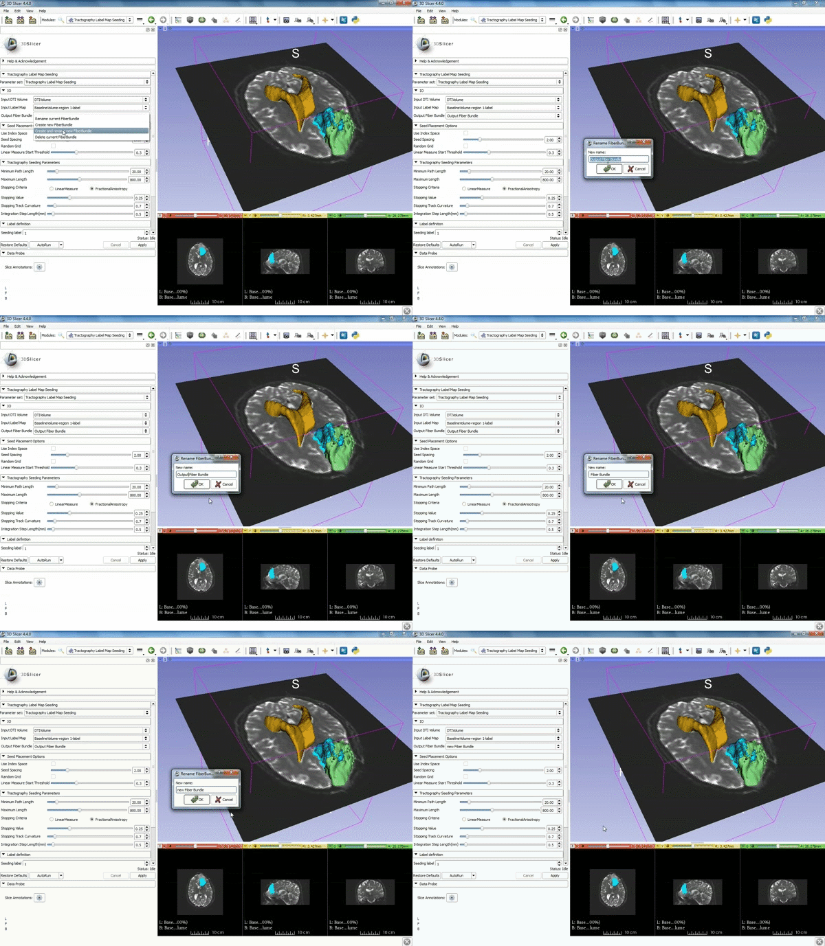
| + | |[[image:a.gif|600px|frame|5. a) For Output Fiber Bundle select "Create and | ||
| + | rename newFiberBundle". b)When the pop-up appears rename the fiber bundle to to "newFiberBundle". ]] | ||
| + | |- style="height: 100px;" | ||
| + | |[[image:b.gif|600px|frame|6. a) Under the Seed Placement Options: Check the Use Index Space. b) Under Tractography Seeding parameter set the stopping value to "0.15" and make sure for Stopping Criteria that "Fractional Anisotropy" is selected. ]] | ||
| + | |- style="height: 100px;" | ||
| + | |[[image:d.gif|600px|frame|7. Under Label Definition set the "Seeding Label" to 293, and Click on Apply]] | ||
| + | |- style="height: 100px;" | ||
| + | |} | ||
| + | </div> | ||
| + | |||
| + | ===Tractography exploration of the ipsilateral and contralateral side === | ||
| + | |||
| + | <div style="width: 62%; height:525px; overflow:auto; border: 2px solid #088; margin: 1em auto 1em auto;"> | ||
| + | {|style="width: 62%; height: 200px;" border="1" | ||
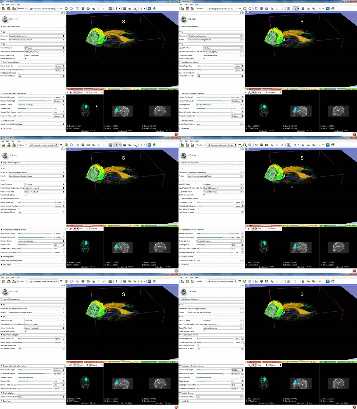
| + | |[[image:l.gif|600px|frame|1. a) Click on the Modules menu and select the module | ||
| + | Tractography Interactive Seeding after selecting "Diffusion" then selecting "Diffusion Tensor Imaging". b) For the Red Slice view position the mouse over the pin icon and change the volume to DTIVolume.]] | ||
| + | |- style="height: 100px;" | ||
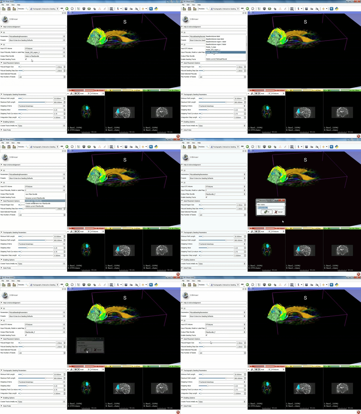
| + | |[[image:m.gif|600px|frame|2. Select the Fiducial icon located at the top, and position the F-1 point next to the cystic part of the tumor by clicking near it | ||
| + | in the 3D viewer.]] | ||
| + | |- style="height: 100px;" | ||
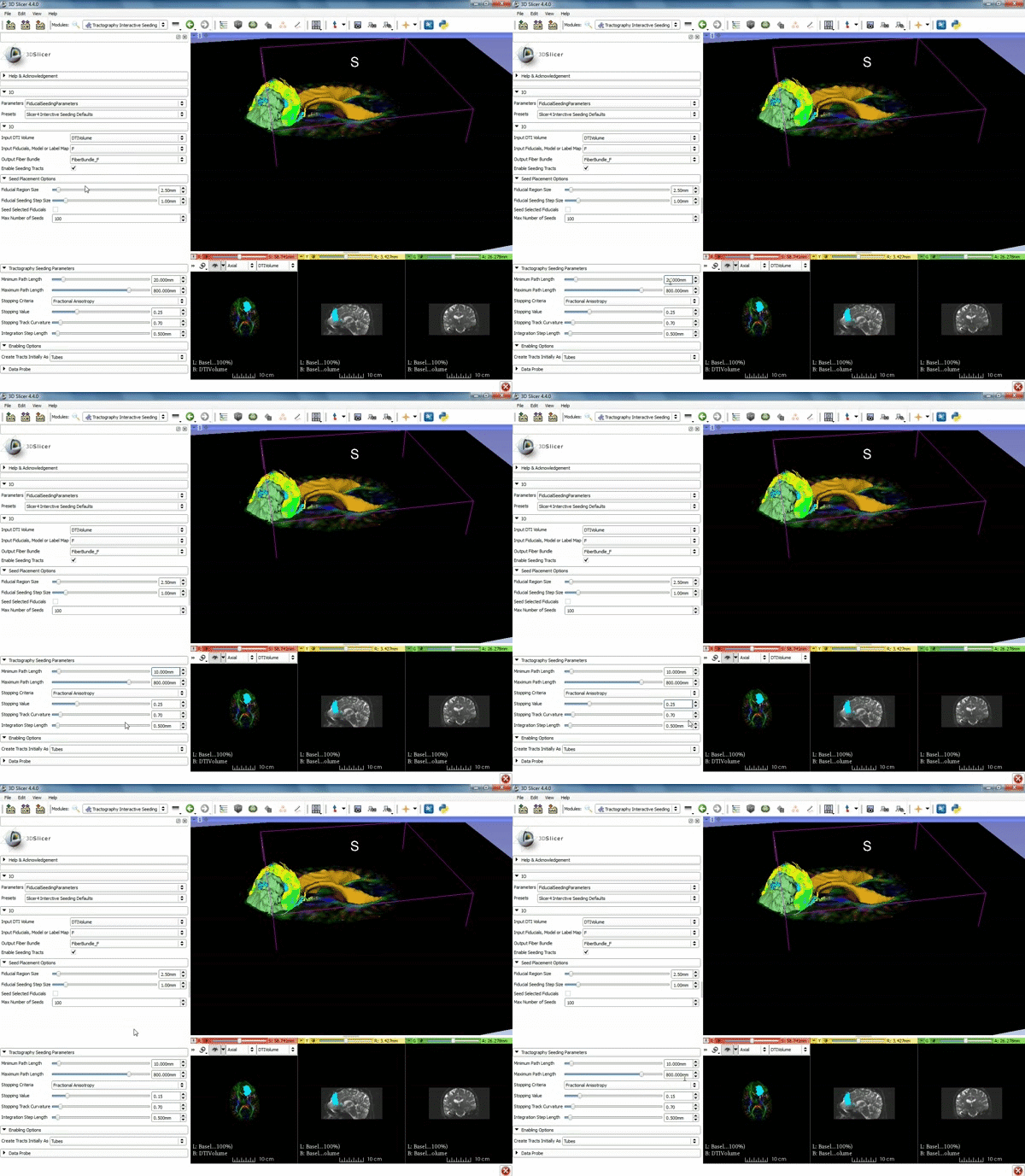
| + | |[[image:n.gif|600px|frame|3. Under IO set Input DTI Volume to "DTIVolume", set Fiducial List or Model to "F", set Output Fiber Bundle to "Create new Fiber Bundle", then click ok for the pop-up. ]] | ||
| + | |- style="height: 100px;" | ||
| + | |[[image:o.gif|600px|frame|4. Under the "Tractography Seeding Parameters" set the Minimum Path Length to 10.0 mm and the FA Stopping Value at 0.15 ]] | ||
|- style="height: 100px;" | |- style="height: 100px;" | ||
|} | |} | ||
</div> | </div> | ||
Latest revision as of 20:24, 9 July 2015
Home < Documentation < 4.4 < gif tutorial|
Contents
Loading DTI and Baseline Data
Segmentation
