Difference between revisions of "Documentation:Nightly:Registration:RegistrationLibrary:RegLib C20"
From Slicer Wiki
| Line 19: | Line 19: | ||
== Download (from NAMIC MIDAS) == | == Download (from NAMIC MIDAS) == | ||
*[http://slicer.kitware.com/midas3/download/?items=xx '''RegLib_C20.mrb''': input data, masks and result transforms <small>(Slicer mrb file. 12 MB). </small>] | *[http://slicer.kitware.com/midas3/download/?items=xx '''RegLib_C20.mrb''': input data, masks and result transforms <small>(Slicer mrb file. 12 MB). </small>] | ||
| + | |||
| + | == Screencasts / Video == | ||
| + | # | ||
| + | RegLib_C20_1_DisplayAndCenter.mov | ||
== Keywords == | == Keywords == | ||
Revision as of 17:28, 28 August 2013
Home < Documentation:Nightly:Registration:RegistrationLibrary:RegLib C20Contents
Slicer Registration Library Case #20: Align PET/CT pair follow-up to baseline
Input
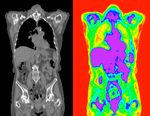
| fixed image/target baseline PET/CT |
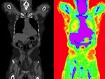
moving image follow-up PET/CT |
Modules used
Download (from NAMIC MIDAS)
Screencasts / Video
RegLib_C20_1_DisplayAndCenter.mov
Keywords
PET/CT, full-body, intra-subject, nonrigid
Procedure
It is possible to perform both steps of affine and BSpline registration in a single pass within the General Registration (BRAINS) module, but to better show/judge progress we perform each separately and feed the results of one the the next step. Hence we first run an affine registration, then use that as starting point for a BSpline registration.
- Load & Center Volumes:
- the original unregistered PET/CT pair have very different image origins. When loaded into Slicer there is very little overlap between the two sets. We first re-center all the volumes to correct for this. Alternatively you can select the "Center Volume" option in the File dialog when loading the images.
- open to the Volumes module
- Active Volume: CT_1
- scroll down and click on the Center Volume button.
- repeat for "CT_2", "PET_1" and "PET_2" volumes
- Set the display properties:
- the CT and PET have very distinct colormaps. Slicer provides presets for both types
- open to the Volumes module
- Active Volume: CT_1
- Window/Level editor presets: click on the "CT-abdomen" button (3rd from the right).
- repeat for volume "CT_2"
- for "PET_1" and "PET_2" select the "PET" preset (3rd from the left)
- since zero in the PET colormap is red, we set a threshold to suppress this: from Threshold menu, select "Manual" and set the left/lower threshold to ~ 600. You can also drag the pop-up slider until most of the red background turns to black.
- Compute Affine Registration: open to the General Registration (BRAINS) module
- Input Images: Fixed Image Volume: CT_1
- Input Images: Moving Image Volume: CT_2
- Output Settings:
- Slicer Linear Transform: (create new transform, rename to: "Xf1_Affine")
- Output Image Volume: none (we need no resampled volume at this stage, only the transform)
- Initialization: none
- Initialize Transform Mode: switch to Off (there is sufficient overlap)
- Registration Phases: 'check Rigid, Rigid+Scale and Affine only
- Main Parameters:
- increase Number Of Samples to at least 200,000
- Leave all other settings at default
- click: Apply; runtime < 2 min.
- check the result
- Place "CT_1" in the background and "CT_2" in the foreground
- switch to the Data module, verify that the "CT_2" node is inside the newly created "Xf1_Affine" node. The registration module should do that automatically for you. You may see a small "+" next to the "Xf1_Affine" node, click on it to reveal the contents.
- fade between background and foreground to judge the alignment.
- Compute BSpline Registration: return to the General Registration (BRAINS) module
- Input Images: Fixed Image Volume: CT_1
- Input Images: Moving Image Volume: CT_2
- Output Settings:
- Slicer BSpline Transform: Create and rename new. Rename to "Xf2_BSpline"
- Slicer Linear Transform: set to none
- Output Image Volume: Create and rename new. Rename to "CT_2_Xf2" (we need a resampled volume to visualize the result. Nonrigid transforms cannot be visualized on the fly)
- Initialization: for the Initialization transform select the "Xf1_Affine" transform created above.
- Initialize Transform Mode: switch to Off
- Registration Phases: uncheck Rigid+Scale and Affine and select BSpline only
- Main Parameters:
- increase Number Of Samples to 300,000
- set B-Spline Grid Size to 11,11,7
- Leave all other settings at default
- click: Apply; runtime for this will be more than 1 minute, depending on CPU.
- check the result
- Place "CT_1" in the background and "CT_2_Xf2" in the foreground
- fade between background and foreground to judge the alignment.
- Apply transform to PET:
- open the Registration / Resample Volume (BRAINS) module
- Image To Warp: PET_2
- Reference Image: PET_1
- Pixel Type: short
- Warping Parameters / Transform file: "Xf2_BSpline"
- Output Image: create and rename new: "PET_2_Xf2"
- Leave all other settings at default
- click: Apply
- Go to the Volumes module and set the PET colormap and threshold for the new volume:
- Active Volume: PET_2_Xf2
- Window/Level editor presets: click on the "PET" preset (3rd button from the left)
- from Threshold menu, select "Manual" and set the left/lower threshold to ~ 600. You can also drag the pop-up slider until most of the red background turns to black.
- optional: Visualize Deformation: install and use the TransformVisualizer
- open the ExtensionsManager

- locate the Transform Visualizer" extension. Click on the "Install" button
- you will need to restart Slicer to complete the installation. Make sure to save all your work before restarting.
- upon restart, reload "CT1" and "Xf2_BSpline"
- to allow fast interactive use we need to subsample the large CT volumes:
- Go to the Registration / Resize Image (BRAINS) module
- Image To Warp: CT_1
- 'Output Image: create & rename new: CT_1s
- Pixel Type: short
- Scale Factor: 3
- Click Apply. This will create a subsampled version of CT_1 that we can use as reference for the Transform Visualizer.
- under All Modules select the TransformVisualizer
- Input/Deformation: select "Xf2_BSpline"
- "Reference Image: select the "CT_1s" we created above
- Output Model: create & rename new Model. e.g. rename to "Xf2_DeformationModel
- Visualization Mode: e.g. select "Block"
- click Apply. You will see a model of the deformation field in the 3D view.
- Go to the Models module
- select the new model and reduce the opacity for better visibility.
- experiment with other view types, esp. GridSlice , Glyph, Contour.
- open the ExtensionsManager
Registration Results
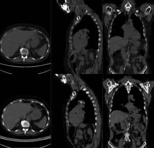 before registration (click to enlarge) before registration (click to enlarge)
|
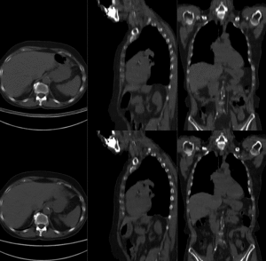 after affine+nonrigid registration (click to enlarge) after affine+nonrigid registration (click to enlarge)
|
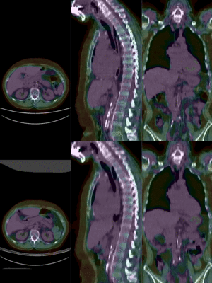 after affine+nonrigid registration (click to enlarge) after affine+nonrigid registration (click to enlarge)
|
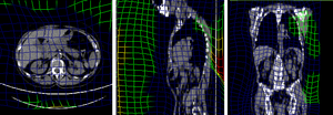 BSpline deformation grid (click to enlarge) BSpline deformation grid (click to enlarge)
|
